
Stereo Balance Meter Circuit

The described circuit operates as a signal balance indicator, typically used in audio applications to monitor the equality of left (L) and right (R) audio signals. The operational amplifier U1 plays a crucial role in this setup. When the L and R signals are equal, the output from U1 remains inactive, resulting in no output signal. Under these conditions, pin 6 of the operational amplifier stabilizes at 4.5 V, indicating a balanced state.
In scenarios where the audio signals are unbalanced, the circuit responds by varying the brightness of connected LEDs. This variation in brightness serves as a visual representation of the degree of imbalance between the left and right audio channels. A greater disparity in signal levels will lead to a more pronounced difference in LED brightness, allowing users to easily identify issues in audio balance.
The circuit may include additional components such as resistors and capacitors to filter noise and stabilize the voltage levels. Proper selection of these components is essential to ensure the circuit's responsiveness and accuracy in detecting signal imbalances. Furthermore, the use of a dual power supply may be necessary to provide the required voltage levels for optimal operation of the operational amplifier.
Overall, this circuit serves as an effective tool for audio engineers and technicians to maintain proper audio balance, enhancing the listening experience by ensuring that both channels are equally represented. When L R signals are equal, no output is present from Ul, and pin 6 is at a steady 4.5 V. Unbalanced audio causes the LEDs to vary in brightness, which causes a difference that corresponds to unbalance between channels.
Related Circuits
The tone generator was a straightforward project developed as a test unit for a customer design job. It utilizes two analog switches controlled by microprocessor code: one switch manages the signal directed to the operational amplifier that drives the...
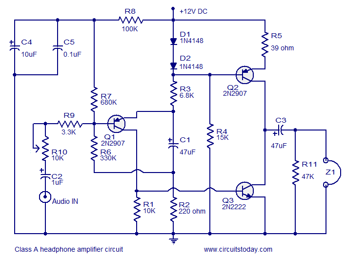
Transistor amplifier circuits that are simple and easy to construct. This includes a headphone amplifier, a four-transistor amplifier, and a low-power amplifier. Transistor amplifier circuits are fundamental components in electronic design, offering various applications ranging from audio amplification to signal...
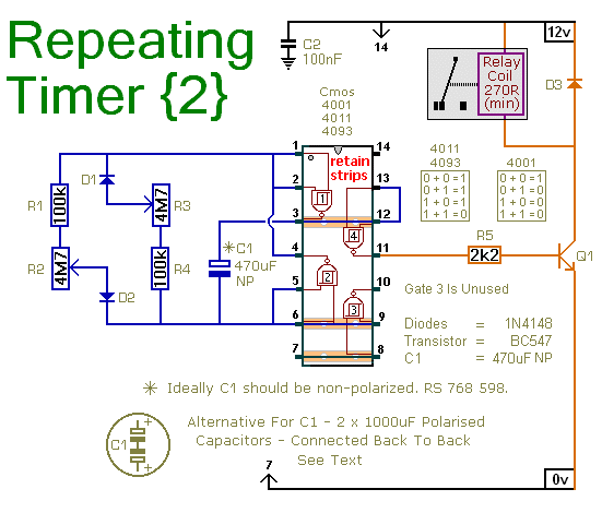
This circuit is based on a simple asymmetric oscillator. The duration for which the relay remains energized and the duration for which it remains de-energized are independently set. With the component values indicated in the diagram, both durations are...
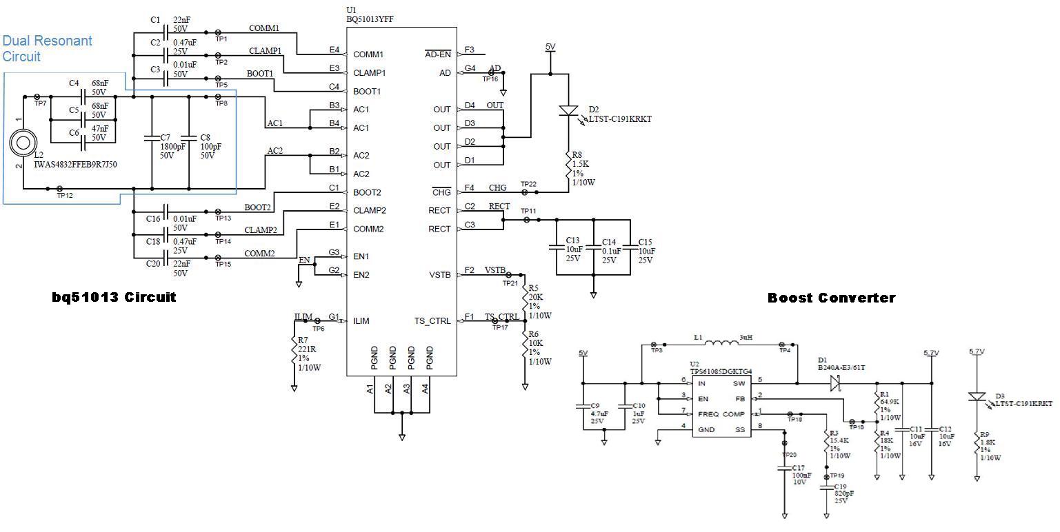
Several boards have been constructed using the bq51013 EVM receiver circuit along with a TPS61085 boost converter circuit, designed in SwitcherPRO Design Software, to elevate the voltage level to 5.7 volts. However, when a load of 580 mA, required...
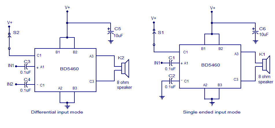
The BD5460 is a low power Class D amplifier that can be utilized in low power applications such as handheld audio devices. The BD5460 does not require an LC filter at the speaker output and can be powered by...
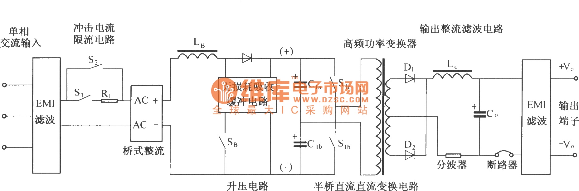
The figure illustrates a simplified schematic diagram of the main circuit DMA12. It primarily consists of the input circuit, an electromagnetic interference (EMI) filter circuit, an impulse current limit circuit, an input rectifier filter circuit, a boost/power factor correction...