
Lc Tuned Amplifiers Circuit

The tuned LC amplifier is a fundamental circuit used in various applications, including radio frequency (RF) amplification and signal processing. It consists of an inductor (L) and a capacitor (C) arranged in a resonant configuration, allowing it to selectively amplify signals at a specific frequency determined by the LC values.
The three output coupling methods provide flexibility in interfacing the amplifier with different circuit stages or loads:
1. **Capacitive Coupling Output**: This method involves using a capacitor to connect the output of the amplifier to the subsequent stage. The capacitor blocks any DC component while allowing AC signals to pass through, ensuring that the amplifier can effectively transmit the amplified signal without affecting the biasing of the next stage. This is particularly useful in applications where DC isolation is required.
2. **Capacitive Tapped Output**: In this configuration, a capacitor is tapped at a specific point in the amplifier circuit, allowing for a portion of the amplified signal to be extracted without affecting the overall operation of the amplifier. This method is advantageous for applications that require a specific signal level or for creating multiple output paths from a single amplifier stage.
3. **Link-Coupled Output**: This coupling method employs a transformer or a similar inductive link to transfer the amplified signal to the next stage. Link coupling is beneficial for impedance matching, as it can help maximize power transfer between stages. It also provides additional isolation and can enhance the frequency response of the overall system.
In summary, the basic tuned LC amplifier's versatility and the variety of output coupling methods available make it suitable for diverse applications in electronic circuits, particularly in RF and audio systems. Each coupling method offers unique advantages, allowing designers to select the most appropriate configuration based on specific requirements and constraints. This basic tuned LC amplifier can be used with three output coupling methods. They are capac-itive coupling output, capacitive tapped output, or link-coupled output.
Related Circuits
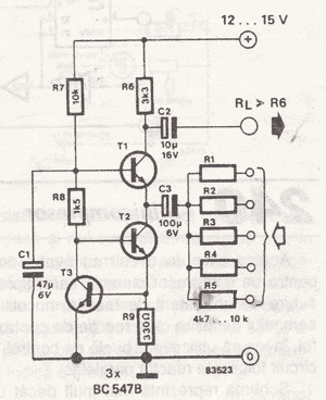
Incorporate resistors in a parallel configuration to enhance audio input. To control the volume for each input channel, integrate a linear trimmer or potentiometer with the following configuration: pin 1 connects to ground, pin 2 serves as the output,...
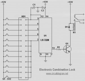
This circuit diagram represents a simple electronic combination lock utilizing the IC LS7220. The circuit is designed to activate a relay for controlling any device (on and off) each time a specific combination of four digits is entered. It...
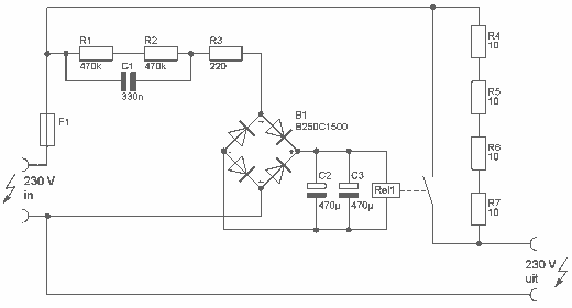
This delay can be used in power amplifiers to prevent the fuses from failing when the amplifier is turned on. The circuit is very simple with a relay that is turned on when C2 and C3 are charged. If...
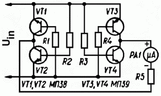
The use of diode rectifiers in AC voltmeters with a low lower limit of measurement range (0.5-1 V) leads to significant nonlinearity of the scale due to the nonlinearity of the current-voltage characteristics of diodes. The incorporation of electronic...
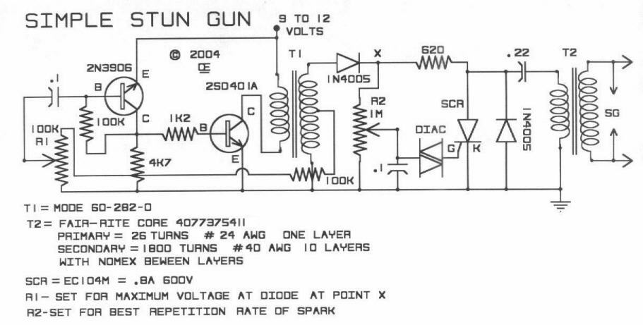
This is a DIY simple stun gun circuit presented solely for educational purposes. There is no recommendation for constructing these stun guns or for their actual use in any capacity. The circuit for a DIY stun gun typically consists of...
This circuit employs a protective resistor R2 along with a feedback resistor R1. Together, these components create a voltage divider that lowers the input voltage amplitude for IC1-a, ensuring that the protective diodes remain inactive. This arrangement enhances the...