
LCD Caller ID with AT89C2051

The described project is a call tracking and display system suitable for various environments such as homes, shops, and offices. It is designed to monitor both incoming and outgoing calls, featuring a built-in Caller ID functionality. The system utilizes a Liquid Crystal Display (LCD) to visually present the incoming and dialed phone numbers, providing users with real-time information about their call activities.
The core component of this system is a microcontroller, which serves as the central processing unit. The microcontroller manages the entire operation of the system, including control over the LCD display and the DTMF (Dual Tone Multi-Frequency) decoder. The DTMF decoder is responsible for interpreting the tones generated by the telephone keypad when dialing a number, allowing the microcontroller to retrieve the dialed digits.
The integration of the microcontroller with the DTMF decoder enables the system to capture and process both incoming and outgoing call data efficiently. When a call is received, the Caller ID information is decoded and sent to the microcontroller, which then formats this data for display on the LCD. The LCD serves as the user interface, providing a clear and accessible means of viewing call information.
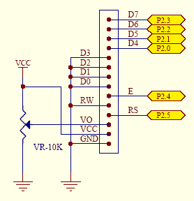
In terms of the schematic design, the microcontroller would be connected to the DTMF decoder through a series of digital input pins, allowing it to read the decoded signals. The LCD display would be interfaced using either a parallel or serial communication protocol, depending on the microcontroller's capabilities and the desired complexity of the design. Additionally, power supply considerations must be made to ensure stable operation of all components, with appropriate voltage regulation and filtering to minimize noise.
Overall, this project showcases a practical application of microcontroller technology in telecommunications, enhancing the ability to track and manage call information in real-time.This Project can be used in home, shops, offices etc. It keeps tracking of both Incoming and Outgoing Calls. It has a built in Caller ID. The incoming and the dialed numbers are displayed on the LCD display. The system will display the numbers over the LCD display. The Microcontroller is used to control the whole system it completely control the LCD display and the DTMF decoder. It gets the numbers through the DTMF decoder and display it over the LCD (Liquid Crystal Display). 🔗 External reference
Related Circuits
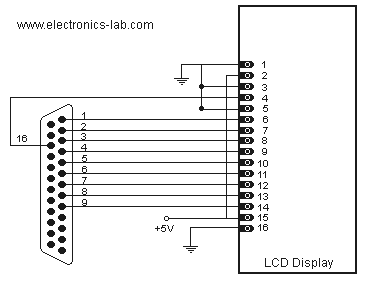
Connecting a LCD display to your personal computer is an easy job. Displaying data from your PC to a LCD can be proven very exciting, so give it a try and build your own today! In this article, we...
The 2x16 Parallel LCD is an 8-bit or 4-bit parallel interfaced LCD. This unit allows the user to display text, numerical data, and custom-created characters. The LCD utilizes the HD44780 series LCD driver from Hitachi or an equivalent controller....
This is an automatic LCD panel backlight control circuit. It is a simple, low-cost implementation of an LED controller that can compensate for aging effects. The automatic LCD panel backlight control circuit is designed to enhance the performance and longevity...
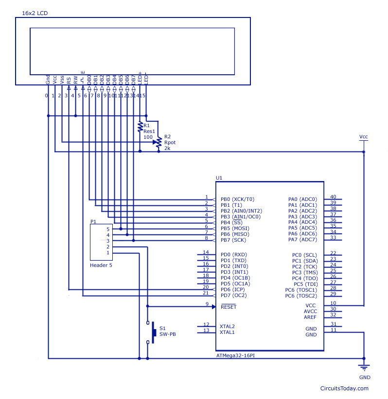
Interfacing an LCD display with AVR microcontrollers, specifically the Atmega8 and Atmega32, including a circuit diagram and embedded C code for implementation. The interfacing of an LCD display with AVR microcontrollers, such as the Atmega8 and Atmega32, is a common...
This document provides an example of how to interface with the standard Hitachi HD44780 LCD using an 8051 microcontroller and the SDCC C compiler. A standard 16-character by 2-line LCD module is utilized, as illustrated in the schematic below....
This example implements a clock using 36 lines of Perl code. It displays the time and date, with a small icon called "heartbeat" in the upper right corner. The "heartbeat" icon, added by the LCDd server, blinks intermittently to...