
LCD to USB interface

LCD2USB utilizes several projects to achieve its objectives. It is based on LCD4LINUX, a framework for using small LCDs with Linux; AVR-USB, a pure software implementation of USB for the AVR platform; USBtiny, another software USB implementation for the AVR; and Peter Fleurys LCD routines for the AVR.
The LCD2USB circuit is primarily centered around the Atmel AVR Mega8 microcontroller, which serves as the core processing unit. The microcontroller is equipped with 8 KBytes of flash memory and 2 KBytes of RAM, allowing it to handle the necessary software for USB communication and display control. The system's clock is generated using a 12MHz crystal oscillator, which ensures accurate timing for USB data transmission.
The USB interface is implemented in software, utilizing three specific pins on the AVR (PC0, PC1, and PD2) for data signaling. A resistor (R1) is employed to indicate low-speed USB operation to the connected PC. The device is designed to operate within the USB specification, with version 1.1 ensuring that the data lines function at 3.6V, enhancing compatibility with various host systems.
Power management is a critical aspect of the design. The LCD2USB is capable of drawing a maximum of 75mA for standard operation, with the ability to supply up to 100mA for backlighting control through a transistor (T1). Careful consideration is required to avoid exceeding the USB power limits, as the total current supply from the USB port cannot exceed 500mA.
Firmware updates are facilitated through a dedicated 10-pin ISP connector, enabling easy programming of the AVR's flash memory. A DIY programming cable is sufficient for this purpose, and various software tools are available for uploading firmware.
The physical design includes a USB B connector mounted on the solder side of the PCB to prevent damage during connection. The alternative option of direct cable attachment is also supported, providing flexibility in installation.
Overall, the LCD2USB project exemplifies an effective integration of readily available components to create a functional USB interface for HD44780 based LCD displays, supported by a robust software framework.LCD2USB is a open source/open hardware project. The goal of LCD2USB is to connect HD44780 based text LCD displays to various PCs via USB. LCD2USB was meant to be cheap and to be made of easily available parts. It is therefore based on the Atmel AVR Mega8 CPU and does not require any difficult to obtain parts like separate USB controllers and the like. The total cost (without display and pcb) are about 5 to 10 Euros. LCD2USB currently comes with a simple demo application that works under Linux, MacOS X and Windows. LCD2USB is currently supported by lcd4linux (LCD2USB support is built-in), LCD Smartie (requires a seperate driver), and LCDProc (LCD2USB support is built-in). The hardware of the LCD2USB interface consists of the Atmel AVR Mega8 CPU, a cheap and easy to obtain microcontroller with 8 KBytes flash (of which ~3k are used in this application) and 2 KBytes RAM.
The processor is surrounded by few parts, mainly connectors to interface to the PC and the LCD. A power LED (LED1) indicates that the system is powered via USB. The system clock is derived from a 12Mhz crystal. This frequency is necessary due to the fact that the software USB implementation requires a precise timing with respect to the USB. The USB interface of the LCD2USB interface is based on a pure software implementation and uses three pins of the AVR (PC0, PC1 and PD2).
This software implementation supports low speed USB only which is signalled to the PC by resistor R1. The current version 1.1 of the LCD2USB operates the USB data lines at 3.6V which complies to the USB spec and increases compatibility over version 1.0.
Special care has to be taken with displays with backlighting. The LCD2USB has been designed to draw at most 75mA which is fine for typical LCDs with LED backlighting. This value is also reported to the host PC via the USB configuration. The LCD2USB interface hardware is able to supply up to 100mA via its software adjustable backlight control.
This is a limitation of the transistor T1. If the backlighting draws more than 100mA, transistor T1 has to be replaced (see the section "part list remarks" below for more details) and special care has to be taken not to overload the USB which can source at most 500mA in total to a bus powered device. An increased backlight current should be reflected in the USB configuration of the device by adjusting the value of USB_CFG_MAX_BUS_POWER in the file usbconfig.h of the firmware sourcecode.
You'll then have to recompile the firmware to make it signal its increased power consumption via USB. These firmware changes may not be necessary with all PCs but some may even shut down the power supply for a device that actually draws more current than its USB descriptors indicate.
The firmware is uploaded using the standard 10 pin AVR ISP connector (SV1). A separate programming cable is required to load the firmware onto the LCD2USB. A simple do-it-yourself cable will be sufficient. A PC software like e.g. Ponyprog or UISP will then be used to upload the firware via this cable to the AVR on the LCD2USB device. The programming cable is only required once, since the firmware is permanently stored in the AVRs internal flash memory.
The USB connection may be done via a USB B style connector. This is the square connector that is typically used for USB devices (unlike the flat A style connector used at USB hosts). The USB connector is to be mounted at the solder side (the rear side of the PCB without the white printing).
Mounting it to the component side may damage the LCD2USB or even the PC when plugging it in. Alternally a cable may directly be attached to the component side of the board as depicted in the image below. Every now and then i have spare PCBs available. Send me an email if you are interested. LCD2USB makes use of several projects to achieve this goal. LCD2USB is based on: LCD4LINUX, a great framework to use small LCDs with linux, AVR-USB, a pure software implementation of USB for the AVR plattform, USBtiny, another software usb implementation for the AVR, and Peter Fleurys LCD routines for the AVR
🔗 External reference
Related Circuits
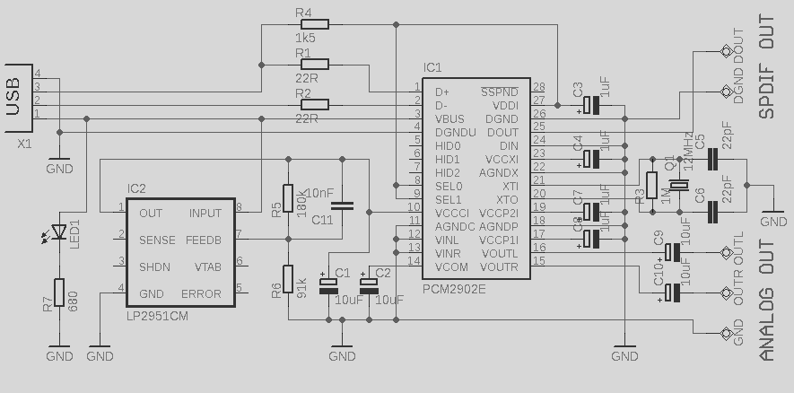
This circuit is a quality preamplifier with a built-in USB DAC designed for the Leachamp power amplifier. The schematic is based on the PCM2902 datasheet. The circuit includes a DAC and ADC, SPDIF input and output, and features three...
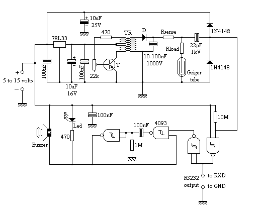
The circuit employs common building blocks. The high-voltage power supply is a classical oscillator circuit utilized in various applications where low current and high voltage are required. The transformer (TR) is a step-up transformer salvaged from a xenon light...
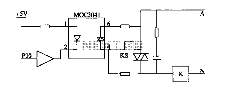
Device for an intermediate relay. The circuit utilizes a Triac AC contactor interface, employing the MOC3041 Triac output optical coupler to trigger the Triac. When Pl0 is low, the Triac will be activated, energizing the AC contactor coil. The described...
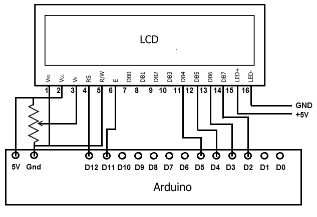
To achieve this, the first step involves establishing the necessary physical connections between the Arduino board and the LCD. Following this, code must be written to display the desired text on the LCD. LCDs have become the standard means...
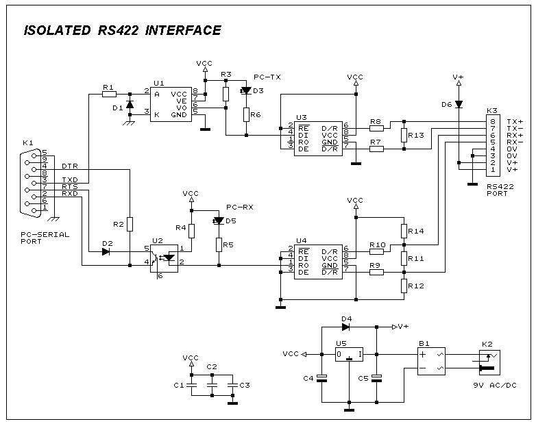
This interface circuit provides electrically isolated RS422 communication interface to the PC serial port. The isolation circuit protects the PC from direct connection to hazardous voltages. More: Figure 1 shows the circuit diagram of RS422 interface. Connector K1 is...
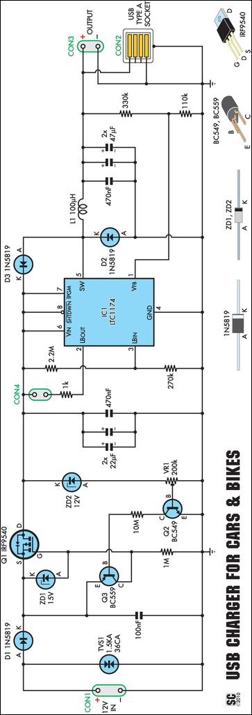
An efficient USB charger designed to operate from a 12V car battery, achieving up to 89% efficiency and capable of charging USB devices at currents up to 525mA. It does not drain the battery if left permanently connected, provided...