
usb audio interface based dac pcm2902

The circuit operates as a high-fidelity preamplifier, integrating a USB DAC to facilitate digital audio playback. The PCM2902 serves as the core component, handling both digital-to-analog conversion and analog-to-digital conversion, making it versatile for audio applications. The SPDIF input and output enable seamless integration with various digital audio sources and destinations.
The power supply for the DAC is critical; thus, the choice of the LP2951CM low-dropout regulator ensures stable voltage levels, minimizing noise and ripple that could affect audio quality. The design employs a fixed output voltage of 3.7 V, achieved through a resistor divider network, which stabilizes the power supply for the DAC.
The circuit board layout is meticulously designed to maintain the integrity of both digital and analog signals. The separation of grounds is essential to prevent digital noise from interfering with the analog audio path. The single-point connection at the USB connector helps to minimize ground loops and potential interference.
The incorporation of a low-pass filter at the DAC output is a standard practice in audio circuit design. By attenuating frequencies above the audio band, the filter helps to eliminate unwanted artifacts from the oversampling process, ensuring cleaner audio playback. The choice of a simple RC filter with a resistor value of 1 kΩ and a capacitor value of 4.7 nF strikes a balance between simplicity and effectiveness. The recommendation for a ceramic capacitor further enhances performance due to its low equivalent series resistance (ESR) and stability.
Adjusting the cutoff frequency by varying the capacitor value to 3.3 nF allows for fine-tuning of the filter's response, catering to specific audio requirements or preferences. Overall, this circuit design exemplifies a thoughtful approach to high-quality audio amplification and playback, ensuring compatibility with contemporary digital audio sources while maintaining fidelity throughout the signal chain.This is the circuit quality preamplifier with built-in USB DAC for my Leachamp power amplifier. Scheme is PCM2902 datasheet. Circuit includes DAC and ADC, SPDIF input and output of HID and with 3 buttons + MUTE, VOL-and VOL. For playback of high quality needed for external low-drop voltage stabilizer for the DAC. LP2951CM DAC is used, which was re adily available in local stores. Output voltage is fixed at about 3. 7 V with two resistors. Circuit board is designed with regard to the placement of good land, and the separation of digital and analog ground. These earth are connected in a single point in a USB connector. The PCM2902 data sheet is recommended to connect a low pass filter the DAC output to filter high frequencies above audioband produced by the conversion of oversampling.
Digital integrated circuits that includes LPF filter frequency above 100 kHz. In the Notes application filter on the pages of the manufacturer recommends first-order LPF (simple RC) or 2 nd order with amplifiers operating as a preamp that works well. I simple RC LPF with the recommended values R and C 1k 4N7. It is best to use the scroll-type ceramic capacitor in place. I did not hear the difference in sound between the connection filter or not, but with respect to other components in an audio chain is best used.
For maximum cutoff frequency that can change the capacitor value of 3n3 🔗 External reference
Related Circuits
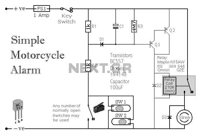
A simple transistor-based motorcycle alarm circuit. This circuit is easy to build and designed to operate at 12 volts. However, by replacing the relay with one that has a 6-volt coil, it can also provide protection at that voltage. The...
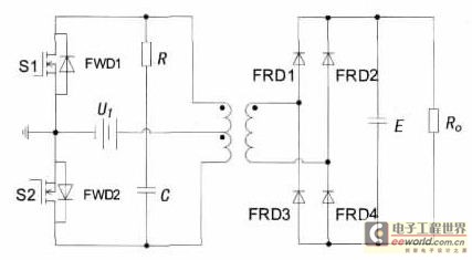
With the increase in the variety of modern electrical equipment for vehicles and the rise in power levels, there is a growing demand for different types of power supplies, including AC and DC sources. The power system needs to...
The lf555afosc1.pdf file download contains a diagram with annotations for a Sub-Tone (CTCSS or "PL") Oscillator, designed using the well-known 555 timer IC configured for astable multivibrator operation. The component values are selected to position the tone range near...
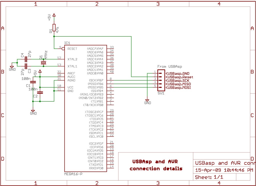
AVRDude is a program designed for burning hex code into microcontrollers. USBasp is a USB-based programmer for AVR microcontrollers. This tutorial will demonstrate how to use AVRdude to burn hex files into an AVR microcontroller using USBasp. The AVRdude...
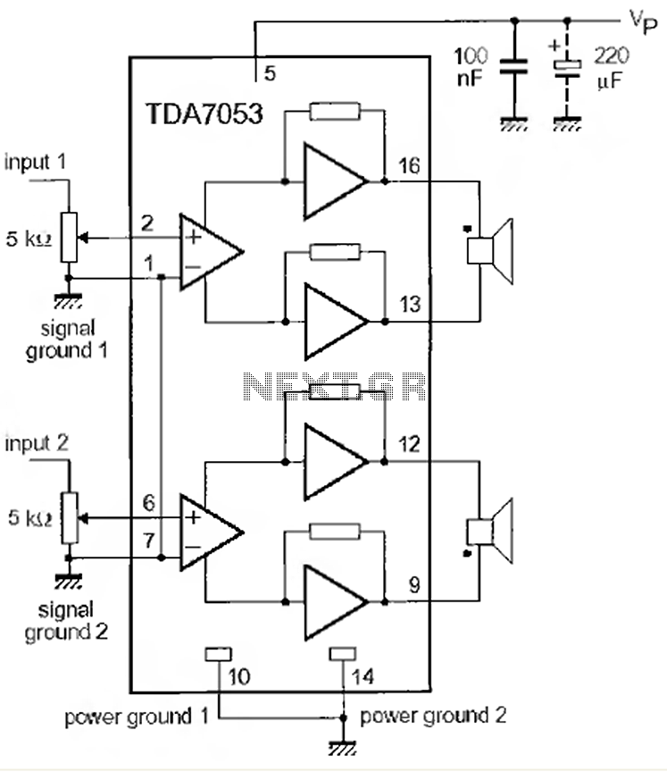
This is a 1-watt stereo audio amplifier circuit utilizing the TDA 7053 integrated circuit from Philips. It is specifically designed for battery operation, delivering 1 watt per channel from a 6V DC supply. The circuit operates optimally between 6V...
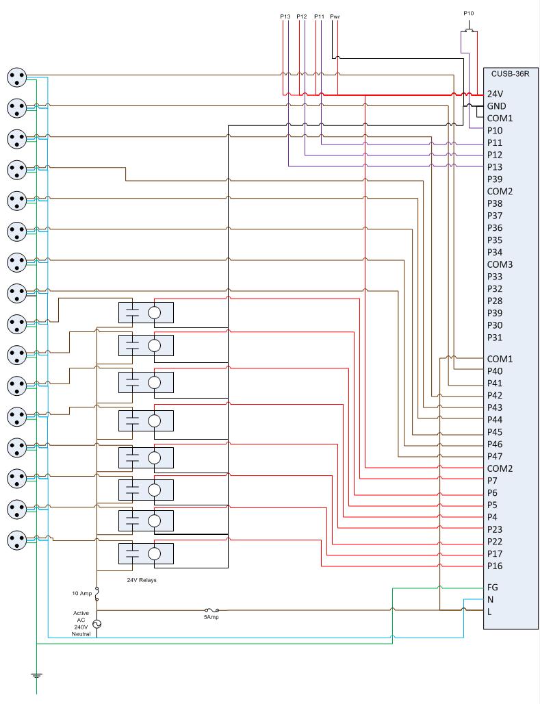
This is the circuit diagram for the Comfile CUSB-36R Programmed Christmas Lights. If it is difficult to read, please contact me via email at [email protected], and I will provide a more detailed schematic. The Comfile CUSB-36R can either drive...