
Lead Acid Battery Charger Circuit

The circuit designed for charging lead-acid batteries incorporates a current-limited power supply alongside a flyback converter topology to ensure efficient charging while protecting the battery from overcurrent conditions. The current-limited power supply serves as the primary source, providing a stable voltage output that is adjustable according to the battery's specifications.
The flyback converter topology is employed to convert the input voltage to a higher output voltage, which is necessary for charging the lead-acid battery effectively. This topology is advantageous due to its ability to isolate the input and output, ensuring safety and reducing the risk of back EMF damaging the power supply.
In the schematic, the power supply is connected to the flyback converter, which includes a transformer, switching elements (such as MOSFETs), and diodes. The transformer is responsible for stepping up the voltage, while the switching elements control the conversion process, allowing for efficient energy transfer. The output from the flyback converter is then fed into the battery through a rectifying diode to prevent reverse current flow, ensuring that the battery is charged correctly.
Additionally, the circuit may include various protective components such as fuses or circuit breakers to safeguard against short circuits and excessive current draw. A feedback mechanism can also be integrated to monitor the battery voltage and adjust the charging current accordingly, maintaining optimal charging conditions and prolonging battery life.
Overall, this circuit design effectively combines a current-limited power supply with a flyback converter for reliable and efficient lead-acid battery charging.To charge lead-acid batteries we can use this circuit that consist of a current-limited power supply and a flyback converter topology. Here is the schematic . 🔗 External reference
Related Circuits
A 2 µF capacitor is charged to approximately 340 volts, and the discharge is controlled by a silicon-controlled rectifier (SCR). A Schmitt trigger oscillator (74C14) and a MOSFET (IRF510) are utilized to drive the low-voltage side of a small...
While traveling, charging a mobile phone can be a significant challenge due to the general inaccessibility of power supply sources, leading to the risk of the battery depleting. To address the issue of mobile phone battery depletion during travel, a...
There are many individuals interested in listening to frequencies within the VHF range of 108 to 132 MHz. This VHF AM converter is designed to convert signals from a frequency band of 106 to 150 MHz, allowing users to...
The Electronic Cash Register (ECR) keeps track of sales transactions quickly and effectively. An abundance of PLUs (Price Look Ups) and department keys accommodate a variety of merchandise items. This means a faster, more accurate check out process and...

A simple instrumentation amplifier circuit diagram utilizing an operational amplifier (op-amp). The equation for gain, along with design, working principles, and construction details, are also provided. An instrumentation amplifier is a type of differential amplifier that has been designed to...
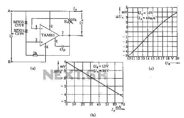
The regulator circuit adjusts the output voltage based on the potentiometer Rp and exhibits linear regulation characteristics. The output voltage Ua varies with the load current Ia, ranging from 0 to 70 mA, as illustrated in Figure (C) for...