
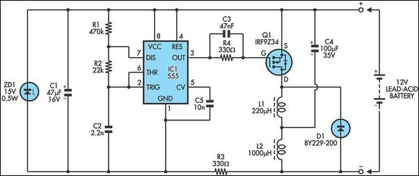
lead acid battery charger with current limit

The lead-acid battery charger with a current limit power supply is designed to safely charge lead-acid batteries while preventing overcurrent conditions that could lead to damage. The circuit typically consists of a transformer, rectifier, voltage regulator, and current limiting components.
The transformer steps down the AC voltage from the mains supply to a lower AC voltage suitable for charging the battery. This AC voltage is then converted to DC using a rectifier, which can be either a full-wave or half-wave rectifier configuration, depending on the design requirements.
Following the rectification process, a smoothing capacitor is employed to filter out the ripple voltage, providing a more stable DC output. The voltage regulator is crucial in maintaining a constant output voltage, which is essential for the safe charging of lead-acid batteries. Common voltage regulators include linear regulators or switching regulators, depending on efficiency and thermal management considerations.
To implement current limiting, a resistor or a dedicated current limiting circuit is integrated into the design. This component ensures that the charging current does not exceed a predetermined threshold, protecting the battery from excessive charging currents that could result in overheating or damage.
The circuit may also include additional features such as LEDs for status indication, fuses for overcurrent protection, and thermal shutdown mechanisms to enhance safety and reliability. Overall, this charger design emphasizes efficiency, safety, and adherence to the charging characteristics of lead-acid batteries.Lead Acid Battery Charger with Current Limit power supply. Go to that page to read the explanation about above power supply related circuit diagram. 🔗 External reference
Related Circuits
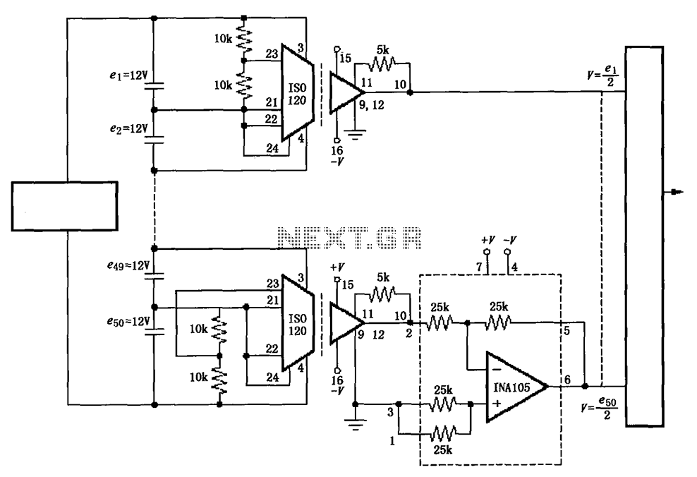
The circuit utilizes the ISO120 and INA105 instrumentation amplifiers to create a battery monitoring system for a 600V battery setup composed of 50 series-connected 12V batteries. This circuit is designed to detect charging and discharging conditions to prevent overcharging...

12V NiCad battery charger with a 200mA/h power supply. Refer to the specified page for an explanation regarding the related circuit diagram. The circuit for a 12V NiCad battery charger designed to supply a current of 200mA/h typically includes several...
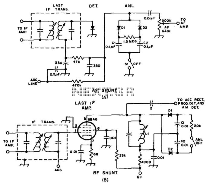
Examples of RF and audio ANL circuits. Positive and negative clipping occurs in both circuits. The circuit is self-adjusting. This noise limiter operates at the IF output. Adequate gain is needed at the IF frequency so that several volts...
In the typical dynamo charging circuit, B+ and B- are the battery connections. D+ and D- go to the dynamo brushes, while DF is the field connection, with its other end returned to D+ inside the dynamo. Please note...
Lead-acid batteries frequently experience premature failure due to overcharging, undercharging, deep discharging, and low electrolyte levels. These conditions can lead to the sulfation of the plates, resulting in high internal resistance and eventual battery failure. Typically, this sulfation process...
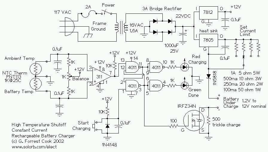
This circuit is designed for a temperature-controlled constant current battery charger, compatible with NiCd, NiMH, and other rechargeable cells. It operates on the principle that most rechargeable batteries exhibit an increase in temperature when they are fully charged. Overcharging...