
Lead Acid Battery Discharge protector

This circuit is designed to monitor and protect lead-acid batteries from over-discharge, a condition that can lead to irreversible damage. The system operates by continuously measuring the battery voltage and providing a visual indication through an LED when the voltage falls below a critical threshold of 10.8V. The core component of the circuit is the LM723 voltage regulator, which functions as a voltage comparator in this application.
The circuit is powered by the battery being monitored, with its terminals connected directly to the battery poles. The LM723 is configured to generate a stable reference voltage of approximately +7.15V at pin IC1/6 when the input voltage exceeds +9.5V. This reference voltage is used to compare against the voltage at pin IC1/4, which is derived from the battery voltage and adjusted by a trimmer potentiometer (TR1).
When the voltage at IC1/4 exceeds the reference voltage at IC1/5, the output at IC1/9 goes low, which turns off the transistor Q1, consequently switching off the LED indicator. Conversely, if the voltage at IC1/4 drops below the reference voltage at IC1/6, the output at IC1/9 transitions high, allowing current to flow through Q1 and illuminating the LED. This visual alert informs the user that the battery voltage has fallen to a potentially damaging level.
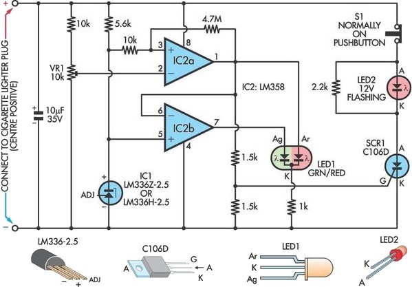
To ensure proper operation, the circuit requires an external regulated supply that maintains a voltage of at least +10.8V. The trimmer potentiometer TR1 is adjusted to set the precise voltage threshold at which the LED activates, ensuring timely warnings before the battery reaches a critical discharge state. This monitoring circuit is ideal for applications utilizing 12V lead-acid batteries, providing a simple yet effective solution for battery management and protection.In perfect discharge the batteries of lead acid, exists the fear they are destroyed. This circuit makes the work, this detection of discharge, protecting the batteries from destruction. At the discharge the polar voltage of batteries 12V of Lead acid, is not allowed it is decreased under 10.8V, thus we have warning with the turn on of Led, when the voltage falls under this price. In order to we achieve the control, we needed a stability voltage and a circuit that could him compare with the checked voltage.
And two these condition provide to IC1- LM 723. The terminal entry of circuit they are connected in the poles of battery. In the IC1/6 is presented a stability voltage + 7.15V, when the voltage of entry is bigger than + 9.5V. The stability voltage is applied in the IC1/5. In the IC1/4 is applied a part of voltage of entry, that is checked by the trimmer TR1. The IC1 is as voltage comparator. Thus when the voltage in the IC1/4 is bigger than the voltage in the IC1/5, then the exit of IC1/9, has low level [ L ], the Q1 is in cutting off and the LED it is off.
In order to it turns on the LED should the voltage in the IC1/4 become smaller than the voltage of reference in the IC1/6, whenever the exit of IC1/9 will become high [ H ], Q1 conduct and the LED turn on. For the regulation of circuit we will need exterior supply, which is regulated has expense + 10.8V, him applies in the entry of him circuit.
We regulate the trimmer TR1, so as to it turns on LED,me the least alleviation of voltage from supply. The terminal entry of circuit, it should they are connected directly in the poles of battery, it can be used where we use batteries 12V of (Lead acid).
🔗 External reference
Related Circuits
This circuit can be utilized as a replacement for the single current-limiting resistor typically found in inexpensive battery chargers. The alternative presented here will prove beneficial over time, as it eliminates the need to discard NiCd batteries after a...
An LED will fail if the current flowing through it is excessively high. This issue can be easily resolved by incorporating a simple resistor in series, which is an effective and low-cost solution. However, as the power supply voltage...
A car battery deteriorates with use, typically lasting no more than four years. Initially, its voltage may drop to just 2V when cranking the engine. As the battery ages, its internal impedance increases, leading to a higher voltage drop...

A simple yet reliable car battery tester circuit diagram. This circuit utilizes the popular and easily accessible LM3914 integrated circuit (IC). The LM3914 is straightforward to operate, does not require external voltage regulators due to its built-in voltage regulator,...
Below is a comparator circuit that can measure the voltage of a car battery in 1-volt steps. The voltage indication is achieved through a comparison mechanism. The described comparator circuit is designed to accurately measure and indicate the voltage level...
Charger for all battery types power supply. This lithium battery charger circuit is dedicated to charging lithium batteries. It uses two chips: the voltage regulator LM317T and ICL7665, which warns microprocessors of overvoltage and undervoltage conditions. Charging is completed...