
LED Audio VU Meter

The described circuit functions as an LED VU meter, which provides visual feedback of audio signal levels across different frequency bands. This versatility allows it to be employed not only in audio mixing environments but also in amplifiers and preamplifiers, where monitoring signal strength is crucial. The design utilizes a single integrated circuit (IC) along with a minimal number of discrete components, making it efficient and cost-effective for various applications.
The circuit features two rectifier stages, which serve to convert the AC audio signals into DC levels that drive the LEDs. This arrangement ensures that the LED indicators provide a responsive visual representation of the audio signal's amplitude, allowing users to gauge levels accurately. The rectifiers are designed to minimize filtering, which enhances the responsiveness of the LEDs to rapid changes in signal level, making it particularly useful for dynamic audio signals.
The schematic likely includes connections for the input signal, power supply, and output to the LEDs. The IC may be responsible for processing the incoming audio signal and controlling the corresponding LED outputs based on the detected signal levels. The discrete components may include resistors and capacitors that help set the gain and response characteristics of the circuit, ensuring that it operates effectively across the intended frequency range.
In summary, this LED VU meter circuit is a practical solution for real-time audio level monitoring, making it an essential tool in any audio engineer's toolkit. Its straightforward design, based on proven application notes from National Semiconductor, ensures reliability and ease of integration into various audio systems.This project is also an essential part of the expandable analyser to be published soon (or perhaps "eventually"), and one meter circuit is used for each frequency band. There are many other uses for a simple LED VU meter. They are ideal as power meters on amplifiers, can be used with mixers (including the high quality mixer described in the project pages), preamps and any other application where it is important to know the signal level.
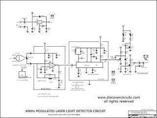
The circuit is completely conventional, and is based on the application notes from National Semiconductor. The circuit is shown in Figure 1 and as you can see it uses a single IC and a few discrete components.
There are two rectifier circuits so that the DC to the LEDs is almost unfiltered. 🔗 External reference
Related Circuits
The circuit presented is an integrated circuit (IC) controlled emergency light. Its key features include automatic activation of the light during mains failure and a battery charger equipped with overcharge protection. In the absence of mains power, relay RL2...
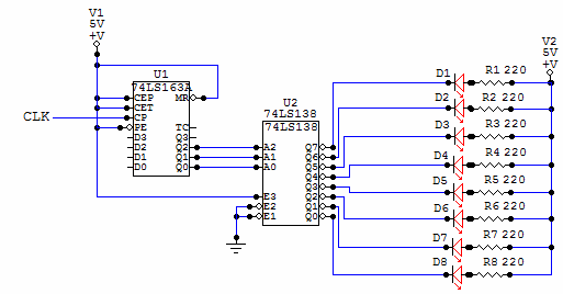
This is a very simple circuit to build, just take note of the control pins on each IC, since both have enable inputs for counting or output, but once set you don't need to worry about them. From left...
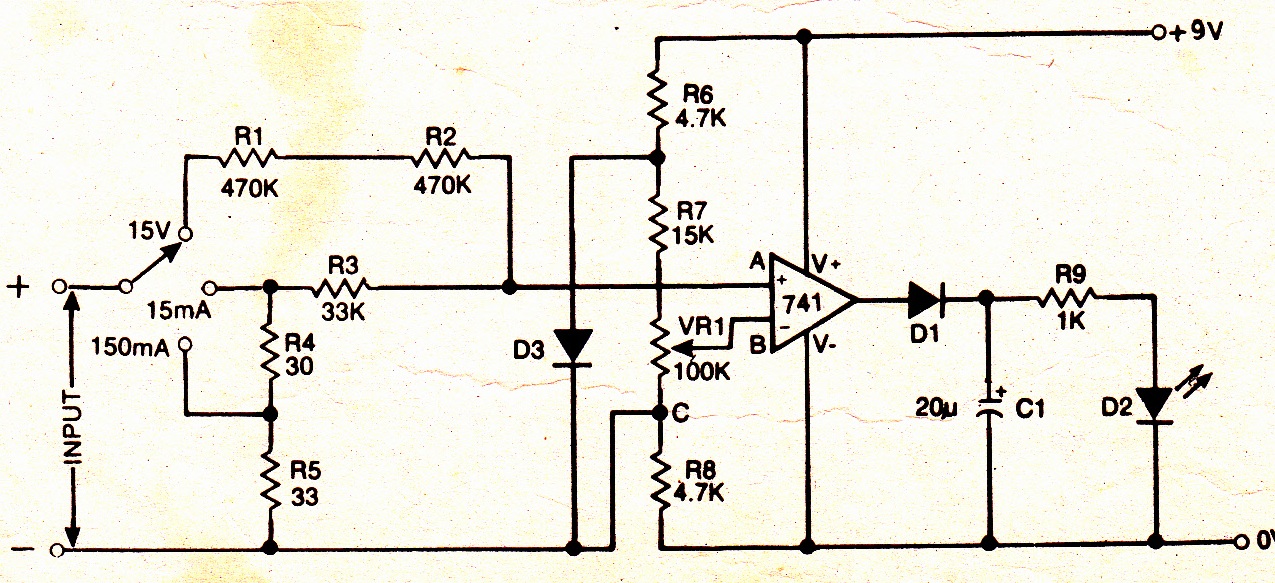
A simple electronic multimeter offers an affordable alternative for hobbyists deterred by the high cost of conventional multimeters. This device is designed to measure three ranges: (i) 0-15V, (ii) 0-15mA, and (iii) 0-150mA, with the possibility of extending the...
It is possible to reduce electricity bills by utilizing alternative power sources. The photovoltaic module, or solar panel, described here, can produce a power output of 5 watts. Under full sunlight conditions, the solar panel generates 16.5V and can...
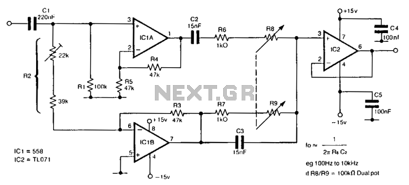
The circuit utilizes a single dual-ganged potentiometer to achieve tuning across a broad spectrum, potentially covering the entire audio range in a single adjustment. The underlying principle is based on the Wien bridge configuration, which is supplied with anti-phase...
Proper grounding is essential for eliminating hum and ground loops. Connect the ground terminals of J1, P1, C2, C3, and C4 to the same point. Connect C6 to the output ground. An audio amplifier is an electronic device that...