
LED runner with 74LS163

The circuit described utilizes a 74LS163 binary counter and a 74LS138 demultiplexer to create a visually appealing LED chaser effect. The 74LS163 is a 4-bit synchronous binary counter that counts up in binary with each clock pulse applied to its clock input. Its enable inputs allow for control over the counting operation, which means that once the circuit is configured, these pins can be set to a stable state to allow continuous counting without further intervention.
The output of the 74LS163 provides binary values that correspond to the current count, which are fed into the 74LS138 demultiplexer. The 74LS138 takes these binary values and activates one of its eight outputs (Y0 to Y7) based on the input address. Each output pin can be connected to an LED, which will illuminate in sequence as the counter increases, creating the moving light effect.
For proper operation, an external clock signal is required to drive the counting process of the 74LS163. This clock can be generated using a simple oscillator circuit or a push-button switch for manual control. The design allows for easy expansion; by utilizing the Q3 output of the counter, it is possible to enable a second 74LS138 demultiplexer, effectively allowing the circuit to control up to 16 LEDs. This can be achieved by connecting the Q3 output to the enable pin of the second demultiplexer, thus doubling the number of sequentially lit LEDs.
Overall, the simplicity and flexibility of this circuit make it an excellent choice for beginners in digital electronics, while also providing opportunities for more advanced modifications and expansions.This is a very simple circuit to build, just take note of the control pins on each IC, since both have enable inputs for counting or output, but once set you don't need to worry about them. From left to right, the first IC is a binary counter, 74ls163, that is used to generate the address numbers we are going to use in the second part of the circuit, the demultiplexer 74ls138.
This Led chaser is built using some very common digital logic circuits. Easy to build, easy to work with, and looks amazing in the dark. This circuit will light each led in sequence, creating a moving light illusion. This demux is the core of the circuit, as this IC pulls low the pin selected in the address inputs. Note that you need an external clock for the counter to work (count). It can also be extended to 16 leds by using the Q3 output of the counter to control the enable inputs of a second demultiplexer, or just add a second one to generate a double pattern. 🔗 External reference
Related Circuits
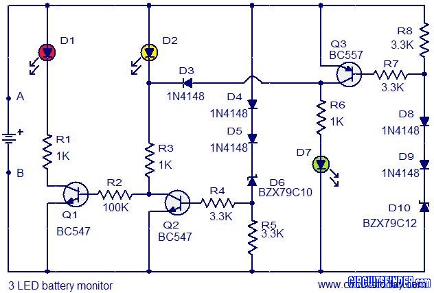
This is the circuit diagram of a 3 LED bar graph type battery monitor circuit that is ideal for monitoring the voltage level of an automobile battery. When battery voltage is 11.5V or less, transistor Q1 will be on...
This is a very simple circuit that can be used to test whether a pot is dry or not. When the two probes are inserted in wet soil, then the resistance between the sensors are low. The base of...
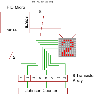
This project demonstrates how to drive a dot matrix LED display consisting of 64 LEDs arranged in an 8x8 configuration or a smaller configuration, such as 35 LEDs arranged in a 7x5 layout. To drive a dot matrix LED display,...

This is a simple hobby circuit for a remote-controlled toy car. The primary component utilized is the IR sensor circuit, which includes a TSOP IR receiver. This receiver allows the user to start and stop the DC motor of...
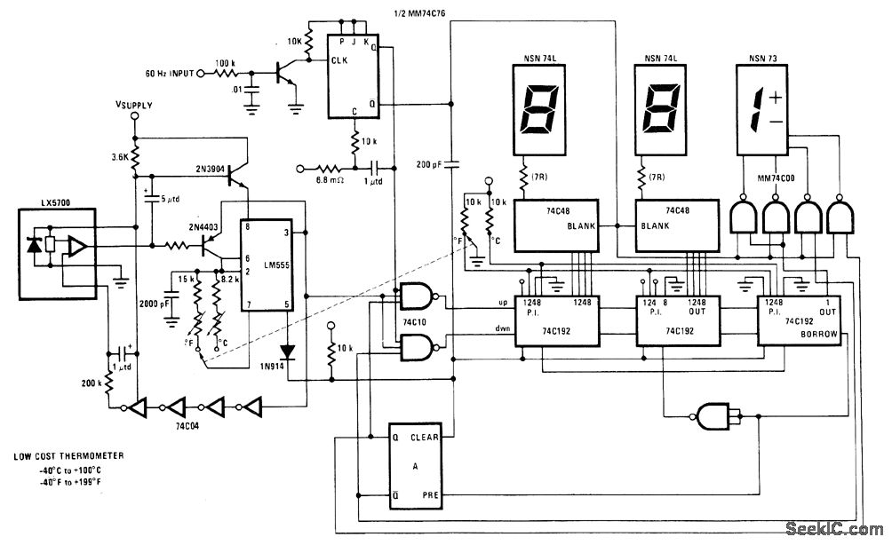
The National LX5700 temperature transducer supplies input to a code conversion circuit that drives a 3-digit LED display. This display indicates temperatures ranging from -40°F to +100°F or -40°F to +199°F, controlled by a ganged switch. The National LX5700...
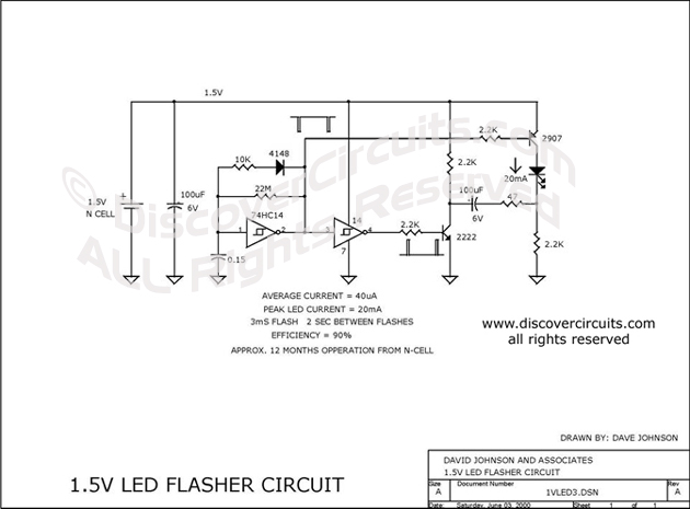
This circuit is designed to extract additional energy from an alkaline battery cell by incorporating two transistors into a configuration similar to a previously mentioned design, thereby enhancing efficiency. A standard 1.5-volt alkaline N cell is capable of powering...