
Led bar-dot level meter

The power meter circuit is designed to visually represent audio signal levels, making it suitable for hi-fi systems. The display consists of a series of LEDs arranged in a linear fashion, where each LED corresponds to a specific power level. The green LEDs illuminate for power levels ranging from 0 to 7, indicating normal operation. When the power level reaches 8, the yellow LED activates, serving as a warning that the signal is approaching its peak. Finally, the red LEDs light up for levels 9 and above, signaling that the system is at or exceeding its peak power threshold, which can help prevent distortion or damage to the audio equipment.
The gain control feature is critical for ensuring accurate readings across different audio devices. By adjusting the gain, users can calibrate the meter to match the output levels of their specific hi-fi system, allowing for precise monitoring of audio performance.
Given the unit's current draw of approximately 200 mA, a dedicated power supply is recommended to ensure stable operation. This can be achieved with a regulated DC power source, which will provide consistent voltage and current, essential for reliable performance. Battery operation could lead to fluctuations in power levels, potentially affecting the accuracy of the readings and the longevity of the battery.
Overall, this power meter circuit provides an effective solution for monitoring audio levels in hi-fi systems, with a focus on user-friendly visual indicators and calibration capabilities.A simple level of power meter can be arranged to give a bar or dot display for a hi-fi system. Use green LEDs for 0 to 7; yellow for 8 and red for 9 to indicate peak power. The gain control is provided to enable calibration on the equipment with which the unit is used Because the unit draws some 200 mA, a power supply is advisable instead of running the unit from batteries.
Related Circuits
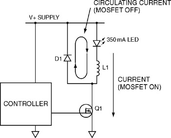
The first switching LED driver to be examined is the buck converter. The buck converter is the simplest type of switching driver and serves as a step-down converter for applications where the load voltage is typically no more than...
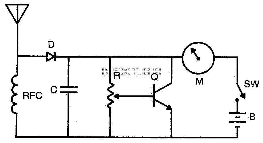
Increased sensitivity provides field strength readings from low-power transmitters. The operating range is 3-30 MHz. To operate, adjust R for Vz to Yz scale reading. RFC = 2 mH choke, C = 1,000 pF, R = 50 K potentiometer,...
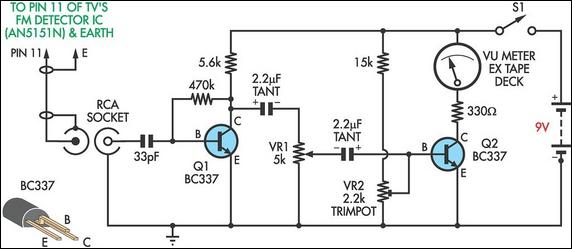
This circuit was designed to assist in the installation of TV antennas. The signal is monitored using a small portable TV set, and this circuit monitors the output of the TV's FM detector IC via a shielded lead. To...
Quad comparators, type LM339. A flyback DC converter, a buck converter, and a step-up converter are involved. The design utilizes several comparators and incorporates multiple LEDs. The concept evolved into a VU meter with a desire for a more...
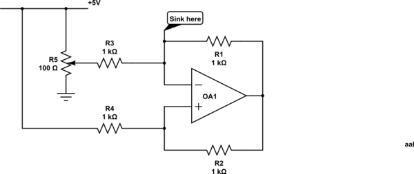
Control a current through several current-mirror devices (specifically the IREF pin on the TLC5940) using a single potentiometer. A modified Howland current source has been utilized, which works adequately with the specified resistor values for dimming an LED. However,...

A voltage-controlled oscillator (VCO) operates similarly to a voltage-to-frequency converter (VFC). Its output frequency is determined by a control voltage input. In the circuit diagram, 'd' represents the amplifier input voltage, which is set to 0.6V, while 'h' denotes...