
LM359 Voltage Controlled Oscillator Circuit

The voltage-controlled oscillator (VCO) is a critical component in various electronic applications, including phase-locked loops (PLLs), frequency modulation, and signal generation. The core functionality of the VCO is to produce an output frequency that varies in response to an input control voltage. This allows for precise frequency modulation based on external signals or control inputs.
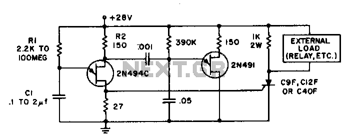
In the described circuit, the operational characteristics hinge on the configuration of the amplifier and the selection of resistors R1 and R2. The relationship between these resistors is crucial; specifically, R2 must be set to twice the value of R1 to ensure that the VCO operates within its intended frequency range. The amplifier input voltage 'd' is critical, as it sets the baseline for the oscillation frequency, while the hysteresis value 'h' of the DM1474 helps stabilize the output and reduce noise.
The ability of the VCO to achieve operational frequencies of up to 5MHz indicates its suitability for high-speed applications. The design must consider factors such as power supply stability, temperature variations, and component tolerances to maintain performance across its operational range. Additionally, proper layout and decoupling techniques should be employed to minimize interference and ensure reliable operation in a variety of environments.Voltage controlled oscillator (VCO) is similar to a voltage to frequency converter (VFC), an oscillator which its output frequency is determined by a control voltage input. This is the figure of the circuit; Where d is the amplifier input voltage = 0. 6V, h=hysteresis of DM1474 (typically = 1V). R2 must beequal to 2R1 for proper operation. Using th is circuit, operation up to 5MHz can be achieved. 🔗 External reference
Related Circuits
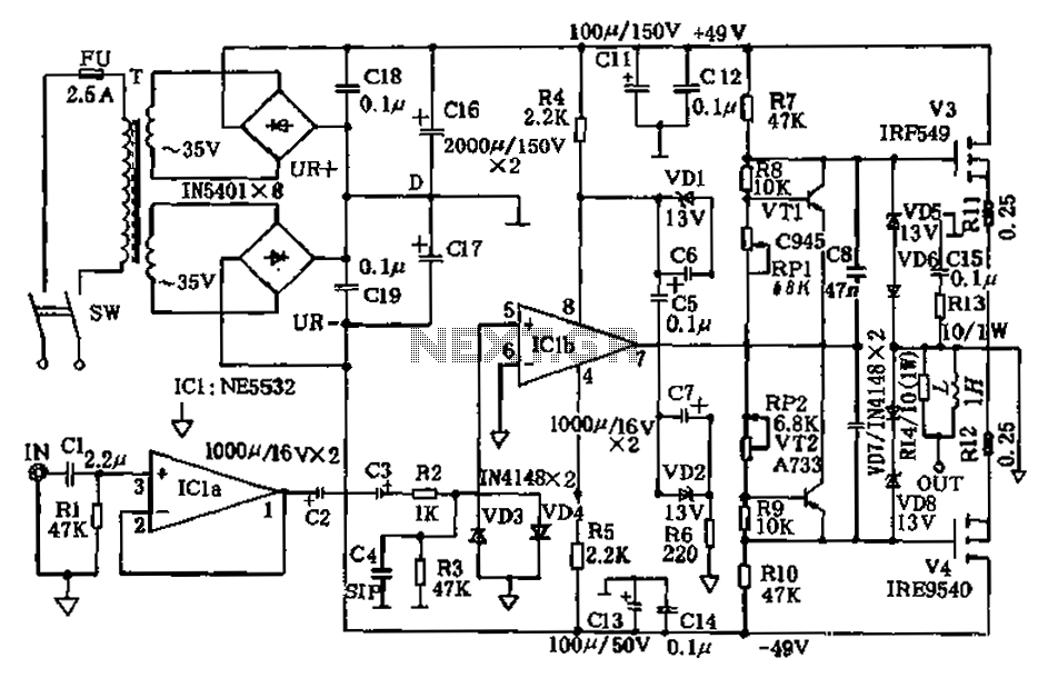
The amplifier circuit presented in this paper introduces a floating power supply aimed at increasing output power. The output power of the amplifier is influenced primarily by the final stage amplifier supply voltage. The circuit's principle is illustrated in...
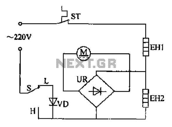
The comb electric circuit illustrated in Figure 1-3 features two temperature settings. By toggling switch S to either the L or H position, different temperatures can be achieved. Once switch S is activated, the circuit powers the heating wires...
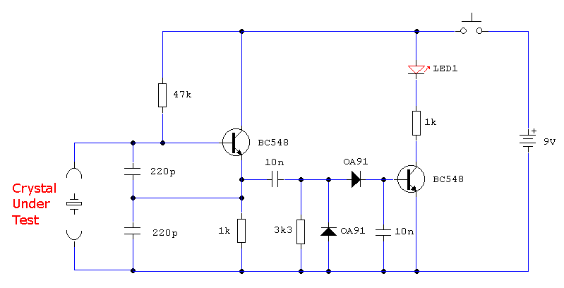
In the first circuit, the BC548 transistor is configured as a Colpitts oscillator, with the frequency being adjusted through the insertion of a crystal. A high-quality crystal will generate high-frequency oscillations, and the output at the collector is rectified...
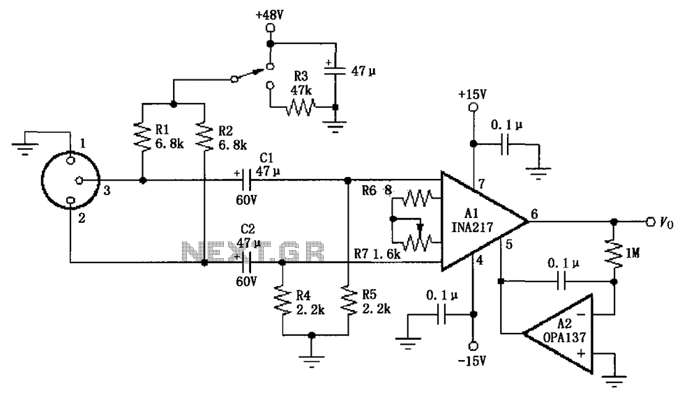
The circuit depicted in the figure consists of an INA217 professional miniature microphone preamplifier. A switch is included to select the use of phantom power. When the switch is connected to +48V, phantom power is enabled; if the switch...
Time delays ranging from 0 milliseconds to over three minutes can be achieved with this circuit without the need for tantalum or electrolytic capacitors. The timing interval begins when power is applied to the circuit. At the conclusion of...
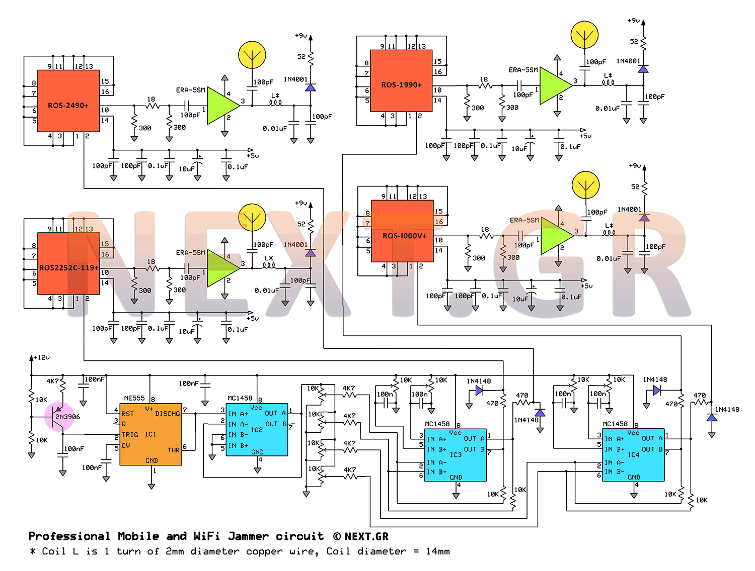
This jammer circuit can be utilized both indoors and outdoors, providing a coverage range of approximately 30 meters to disconnect wireless devices from their communication with the base station. The circuit design employs frequency ranges allocated to mobile operators,...