
LED bar peak program meter display for audio

The described LED bar graph circuit serves as a visual representation of audio signal levels, employing a series of operational amplifiers to process and indicate the amplitude of the incoming audio signal. The LEDs are strategically arranged to illuminate in 6 dB steps, allowing for clear and intuitive visual feedback on the signal strength.
The circuit operates by taking the positive peak envelope of the audio signal, which is fed into the non-inverting inputs of the op-amps. The inverting inputs are set to a series of DC reference voltages that increase in 6 dB steps, effectively creating a threshold for each op-amp. When the audio signal exceeds these thresholds, the corresponding op-amp output goes high, activating the associated LED.
The fast response time of the circuit ensures that it can accurately track rapid changes in the audio signal, making it suitable for dynamic audio applications. The one-second decay time is designed to provide a smooth transition between levels, reducing the perceptible flicker that can occur with rapidly changing signals. This decay characteristic enhances the visual experience, making it easier for users to interpret the audio level without distraction.
In summary, this LED bar graph circuit is an effective tool for visualizing audio levels, utilizing a combination of op-amps and LEDs to provide real-time feedback on signal strength, with carefully calibrated thresholds and response characteristics that enhance usability and accuracy.A bar column of LEDs is arranged so that as the audio signal level increases, more LEDs in the column light up. The LEDs are arranged vertically in 6 dB steps. A fast response time and a one second decay time give an accurate response to transients and a low "flicker" decay characteristic.
On each of the op amps inverting inputs is a dc reference voltage, which increases in 6 dB steps. All noninverting inputs are tied together and connected to the positive peak envelope of the audio signal Thus, as this envelope exceeds a particular voltage reference, the op amp output goes high and the LED lights up. Also, all the LEDs below this are illuminated.
Related Circuits
This is it. It's a STEREO LED LEVEL METER. It's the cheapest and best bar graph display available and best of all, it uses readily available components. You only need a handful of LEDs, 22 transistors, some resistors, diodes,...
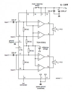
A 2x22 W car audio amplifier circuit utilizes the TDA1558, a monolithic integrated class-B output power amplifier that includes four 11 W single-ended amplifiers or two 22 W bridge-tied load (BTL) amplifiers. The TDA1558 is designed to drive speakers in...
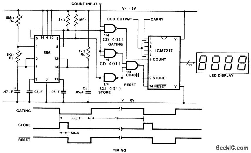
This is an inexpensive frequency counter and tachometer circuit. It utilizes a 556 dual timer to generate the gating, not-store, and not-reset signals for an ICM7217 counter. One timer operates as an astable multivibrator using resistors RA, RB, and...
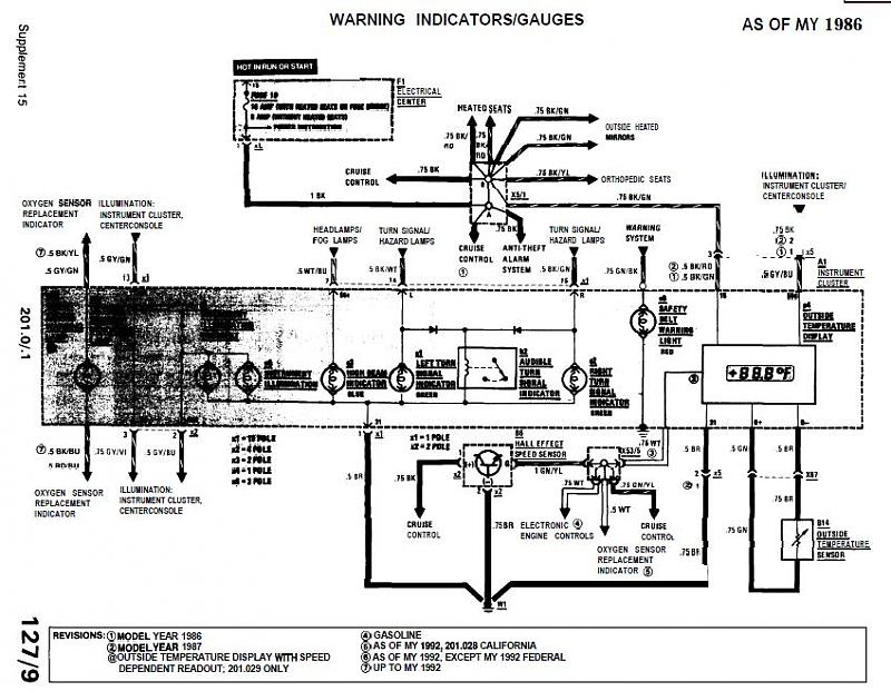
The 1989 2.6 outside thermometer (Celsius) has malfunctioned and stopped displaying readings. A replacement unit was sourced from an eBay seller. The malfunctioning outdoor thermometer likely employs a thermistor or a similar temperature-sensing component to measure ambient temperature. In a...
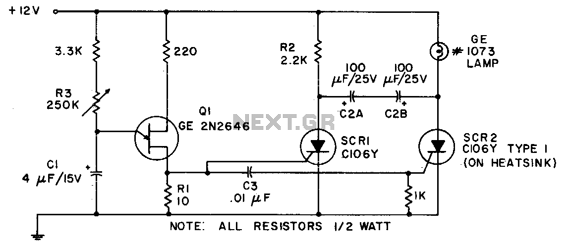
Due to its capability to handle heavy inrush currents, this incandescent lamp flasher utilizes the C106 SCR. The components illustrated allow for the flash rate to be adjusted by potentiometer R3, ranging from 36 flashes per minute to 160...
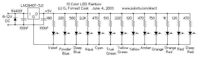
This circuit uses a set of 13 differently colored LEDs to generate a full color spectrum. The photo does not fully represent the colors generated due to camera limitations. The real-world display is very eye-catching. If you want to...