
Auto boat or barricade flasher

The incandescent lamp flasher circuit is designed to provide a variable flashing output using a silicon-controlled rectifier (SCR), specifically the C106 model. This component is essential for managing the high inrush currents that occur when the lamp is initially energized. The C106 SCR operates by allowing current to flow through it when triggered, and it remains conducting until the current drops below a certain threshold, making it ideal for applications requiring robust switching capabilities.
The circuit configuration typically includes a resistive-capacitive (RC) timing network that determines the flash rate of the lamp. The potentiometer R3 plays a crucial role in this network, as it allows for the adjustment of the time constant of the circuit. By varying the resistance, the charge and discharge times of the capacitor can be altered, directly affecting the frequency of the flashing output.
In practice, the flash rate adjustment can be observed through the lamp's brightness and the frequency of the on-off cycling. The range of 36 to 160 flashes per minute provides versatility for different applications, such as decorative lighting or signaling devices. Additional components in the circuit may include diodes for flyback protection, resistors for current limiting, and capacitors for filtering to ensure stable operation.
Overall, this incandescent lamp flasher circuit exemplifies a practical application of SCR technology in controlling lighting effects, with adjustable parameters to suit specific user requirements.Because of its ability to withstand the heavy inrush currents, this incandescent lamp flasher uses the C106 SCR With the components shown, the flash rate is adjustable by potentiometer R3 within the range of 36 flashes per minute to 160 flashes per minute.
Related Circuits

The physical interface bus can be either fiber (optical) or wire (electrical). The distinction lies in the fact that the electrical interface is defined just before the optical encoder. Therefore, the physical interface bus between devices is optical (fiber),...
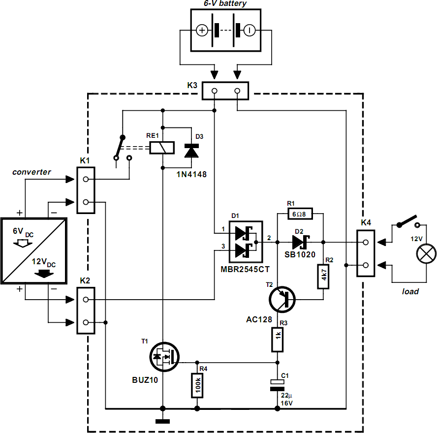
New applications for DC voltage converters, such as the LT1070, arise every day. These converters can be adapted to nearly every imaginable ratio of input and output voltages. However, all of these circuits and devices share a common shortcoming:...

The circuit for automatic brightness adjustment in a television utilizes a photosensitive resistor and a contrast potentiometer connected to an intermediate stage. The photosensitive resistor varies its resistance based on light intensity, causing changes in the potential at the...

The switch control system utilizes sensors to inform the microcontroller of the trains' positions on the layout. This ensures that only one train occupies the main line at any given time and that switches are correctly set for the...

This micro flasher circuit continuously emits a flashing light while consuming very little power. The circuit can operate for an extended period using four 1.5V torch cells. A low-power CMOS IC, the CD4093 (IC1), is utilized to generate sharp...
The electrical wiring diagram for the 1993 VW Passat includes the Engine Control Module, Automatic Control Unit, and Automatic Solenoid. This diagram illustrates the connections and wiring between various components of the vehicle's system, such as the multi-function switch,...