
LED Volt Meter

The LED voltmeter circuit is structured to provide a visual representation of battery voltage levels through a series of four LEDs, each corresponding to specific voltage thresholds. The Zener diodes are strategically selected based on their breakdown voltages, which determine the activation points for each LED.
In this configuration, the first LED may be activated at a voltage of approximately 10.6 volts, indicating a low charge level. The second LED could light up at around 12.0 volts, signaling a moderate charge. The third LED might illuminate at 13.6 volts, indicating a high charge level for a lead-acid battery, while the fourth LED activates at 14.8 volts, representing a fully charged tubular battery.
The circuit operates by connecting the battery terminals to the input of the Zener diodes. As the battery voltage changes, the corresponding Zener diode will reach its breakdown voltage, allowing current to flow through and light up the associated LED. This creates a clear and intuitive display of the battery's charge status.
To enhance the performance and reliability of the circuit, it is advisable to include a current-limiting resistor in series with each LED. This resistor will prevent excessive current from damaging the LEDs while ensuring they operate within their specified parameters. Additionally, the circuit can be powered directly from the battery being monitored, eliminating the need for an external power supply.
In summary, this simple LED voltmeter circuit provides an effective means of monitoring the charge level of lead-acid and tubular batteries through a straightforward visual indicator system, utilizing Zener diodes for precise voltage detection and LED illumination.Here is a Simple LED Volt meter to Monitor the charge level in Lead Acid Battery or Tubular battery. The terminal voltage of the battery is indicated through a four level LED indicators. The nominal terminal voltage of a Lead Acid battery is 13. 8 volts and that of a Tubular battery is 14. 8 volts when fully charged. The LED voltmeter uses four Zene r diodes to light the LEDs at the precise breakdown voltage of the Zener diodes. Usually the Zener diode requires 1. 6 volts in excess than its prescribed value to reach the breakdown threshold level. When the battery holds 13. 6 volts or more, all the Zener breakdown and all LEDs light up. When the battery is discharged below 10. 6 volts, all the LEDs remain dark. So depending on the terminal voltage of the battery, LEDs light up one by one or turns off. 🔗 External reference
Related Circuits
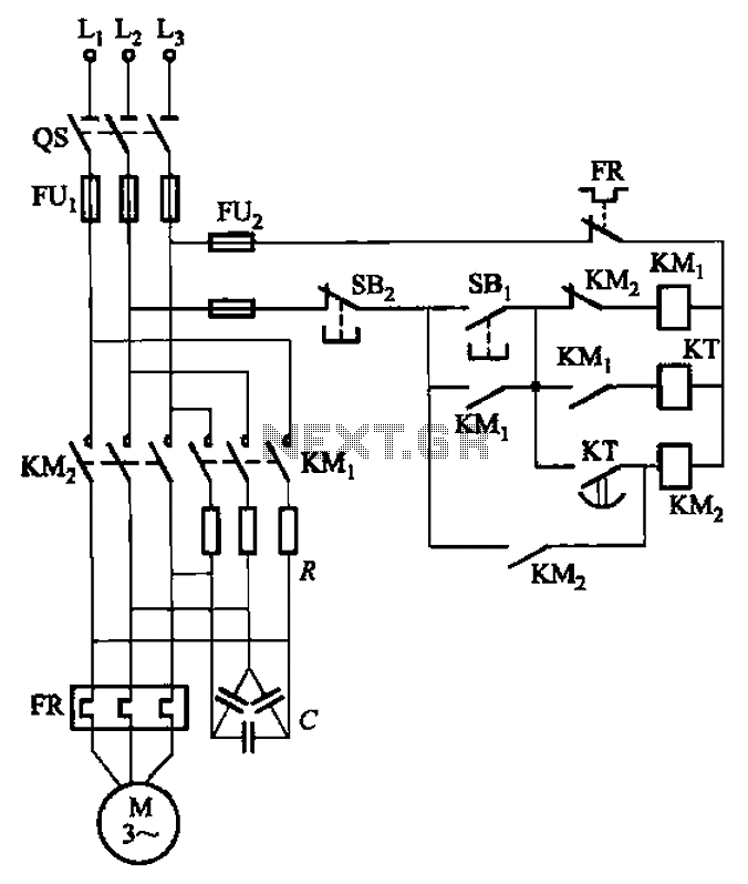
The circuit depicted in Figure 3-35 demonstrates a method for starting a motor that transitions to full voltage through a step-down switching process. This approach provides an uninterruptible power supply, effectively preventing issues related to switching currents that may...
This simple and slightly odd circuit can clearly show the level of the supply voltage (in a larger device): as long as the indicator has good 12 volts at its input, LED1 gives steady, uninterrupted (for the naked eye)...

This circuit is a radio frequency (RF) field strength meter, similar to a previous model but designed to operate with a lower supply voltage using a single 1.5V battery. The schematic diagram of this RF strength meter circuit is...

This project article was originally written in 2004 when most computers had parallel ports. This is no longer the case, so much of this information is now outdated. The Mini RC Car Project has been one of the most...
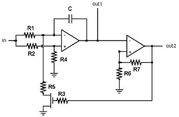
A voltage-controlled oscillator is an oscillator whose frequency of oscillation can be varied by changing an applied voltage. A voltage-controlled oscillator (VCO) is an essential component in various electronic systems, particularly in communication devices, signal processing, and modulation applications. The...
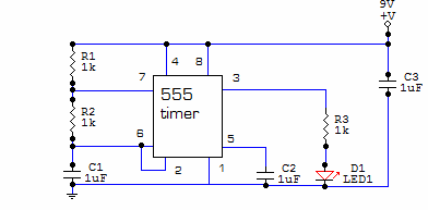
This circuit is built around one of the most popular timer integrated circuits, the 555 timer. It will flash the LED on and off at regular intervals. From left to right, the two resistors and the capacitor set the...