
LED Chaser by IC 4017 + IC 555

The 10 LED Chaser circuit is an engaging project that demonstrates the sequential lighting of LEDs, creating a visual effect akin to a moving light. The core component of this circuit is the CD4017 decade counter, which is a popular choice due to its simplicity and affordability. The CD4017 can drive up to ten output LEDs, making it ideal for this application.
The circuit typically requires a few additional components, including a clock signal generator, resistors, and capacitors. The clock generator can be implemented using a 555 timer IC configured in astable mode, providing a continuous pulse that drives the CD4017. The output of the CD4017 is connected to a series of LEDs, each of which is connected to one of the decade counter's outputs.
A resistor is placed in series with each LED to limit the current and prevent damage to the LEDs. The LEDs will light up in sequence, following the clock pulses, creating a chaser effect as they turn on and off in a cycle.
Power supply considerations are also essential; the circuit typically operates within a voltage range of 3V to 15V, making it versatile for various applications. Proper decoupling capacitors should be used near the IC to stabilize the power supply and ensure reliable operation.
Overall, the 10 LED Chaser circuit using the CD4017 is an excellent project for beginners and enthusiasts, providing a practical introduction to digital electronics and sequential logic.If you want to build a 10 LED Chaser circuit we suggest this circuit first. It uses popular IC is a simple and affordable IC-4017_decade counter and.. 🔗 External reference
Related Circuits
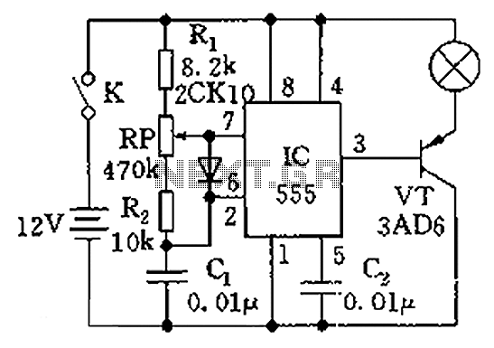
The circuit illustrated in the figure is a dimmer using the 555 timer as the core component. The 555 timer, along with resistors R1, RP, R2, and capacitor C1, forms an astable multivibrator. The oscillation frequency, f, is calculated...
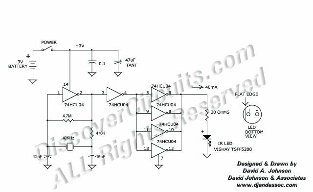
This 40 kHz crystal-controlled oscillator circuit drives an infrared LED with powerful 40 mA pulses. The circuit operates at a frequency of 40 kHz, determined by the crystal oscillator, which provides stable frequency output essential for applications requiring precise timing....
Good preparation. There is one suggestion to use RFM70 or RFM22 for RF communication. The RFM70 and RFM22 are low-power, high-performance RF transceiver modules designed for wireless communication applications. Both modules operate in the 2.4 GHz ISM band, making them...
A 555 timer can be used to generate a square wave to produce a negative voltage relative to the negative battery terminal. When the timer output at pin 3 goes positive, the series 22 uF capacitor charges through the...
I recently purchased 10 SLM1608 (SLM1606) LED matrix display units from Ebay. These are 16x16 LED matrix units with a green and a red LED per pixel allowing each pixel to be switched to either green, red, amber or...
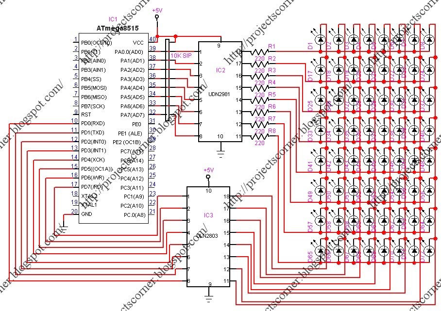
This project involves a scrolling LED display composed of 64 LEDs arranged in a matrix configuration. The anodes of the LEDs are driven by a driver IC, UDN2981, while the cathodes are controlled using the ULN2803. An Atmega8515 microcontroller...