
LED Chaser

The described circuit is a simple LED chaser using a 4011 NAND gate IC, which serves as the primary component for generating the oscillation needed to drive the LEDs. The 4011 contains four NAND gates, and in this application, two of them are configured to create a basic oscillator circuit.
The oscillator operates by utilizing the feedback mechanism inherent in the NAND gate configuration. When powered, the output of one NAND gate is connected to the input of the second, creating a loop that causes the gates to toggle between high and low states. This oscillation produces a square wave signal that can be used to drive a series of ten LEDs arranged in a chaser pattern.
To implement the LED chaser effect, the output from the NAND gate oscillator is further processed using a series of flip-flops or shift registers, which can be constructed from additional NAND gates or other logic ICs. Each flip-flop would control one LED, lighting it sequentially as the signal propagates through the circuit. This provides the visual effect of lights "chasing" each other along the strip of LEDs.
Powering the circuit requires a suitable DC power supply, typically in the range of 5V to 15V, depending on the specifications of the LEDs and the NAND gates used. Current-limiting resistors should be placed in series with each LED to prevent excessive current flow, ensuring longevity and consistent brightness.
The design can be further enhanced by incorporating a potentiometer to adjust the speed of the chaser effect, allowing for customization of the blinking rate. Additionally, the circuit can be expanded to include more LEDs or different configurations, such as bi-directional chasers or varying patterns, by modifying the control logic.
Overall, this simple LED chaser circuit demonstrates the versatility of the 4011 NAND gate and provides an engaging visual display suitable for various applications, from decorative lighting to educational demonstrations in electronics.I don`t know why, but people like blinking lights. You see LED chasers everywhere, in TV shows (Knight Rider), movies, and store windows. This schematic is my version of a simple 10 LED chaser. There is no 555 timer used because at my local electronics store they are over $4 Cdn. Instead, an oscillator made up of two sections of a 4011 NAND gate is employed. This chip is very inexpensive and extremely common. 🔗 External reference
Related Circuits
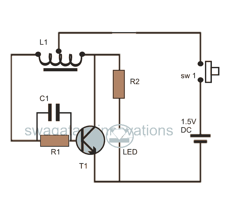
This post discusses blue and white LED drivers utilizing a joule thief circuit. Further exploration of the circuit's functionality is provided, along with simulation points. The joule thief circuit is a simple and efficient boost converter that allows for the...
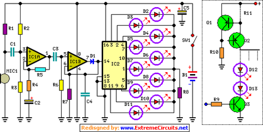
The basic circuit illuminates up to ten LEDs in sequence, following the rhythm of music or speech picked up by a small microphone. The expanded version can drive up to ten strips, each formed by up to five LEDs,...
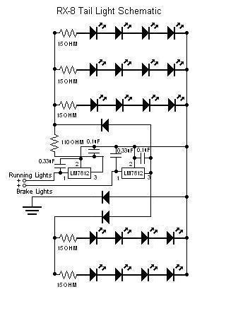
The circuit has been successfully recreated and functions properly when the line connected to the 1 µF capacitor of the "2" terminal of the running lights' LM7812 is not grounded. This line is also connected to the 33 µF...
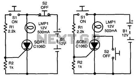
In both circuits, the SCR (Silicon Controlled Rectifier) and the lamp can be latched on by momentarily closing switch S1, which provides gate drive to the SCR through resistor R1. In both configurations, the gate is connected to the...

This project I made for my little daughter. It is 24 channel light illumination. The schematic is very simple 24 LEDs, 1 MCU and some additional components. The main principle is dynamic indication, which is usually implemented for control...
Flyback LED drivers are versatile as they can be utilized in applications with input voltages either above or below the necessary output voltages. They feature a straightforward circuit configuration that maintains a constant LED current without the need for...