
The LED car voltmeter (3)
")
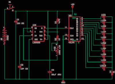
The LED car voltmeter is an essential device for monitoring the voltage levels in automotive applications. The filter circuit plays a crucial role in stabilizing the input voltage by using a 3-terminal voltage regulator (IC1). This regulator ensures a consistent output voltage regardless of input fluctuations, which is essential for accurate voltage measurement. The filter capacitor (C1) is connected to the output of the regulator to smooth any remaining ripples in the voltage signal, thereby enhancing the performance of the voltmeter.
Following the regulator, the voltage distribution filter circuit is designed to divide the voltage levels appropriately for further processing. This circuit consists of multiple resistors (R1-R7) that create a voltage divider network, allowing specific voltage levels to be tapped for amplification. Capacitor (C2) is included in this circuit to filter out high-frequency noise, ensuring that only stable voltage levels are passed to the next stage.
The voltage amplifier circuit utilizes a 6 NOR gate configuration (IC2) to amplify the voltage signals received from the voltage distribution filter circuit. NOR gates are used in this application due to their ability to perform logical operations while also serving as amplifiers. The outputs of the NOR gates (D1-D6) provide a stronger voltage signal that is suitable for driving the LED display circuit.
Finally, the LED display circuit consists of six LEDs (V1-V6) that visually represent the voltage levels. Each LED is paired with a resistor (R8-R13) to limit the current flowing through the LEDs, preventing damage and ensuring longevity. The combination of these components allows the voltmeter to provide real-time voltage readings in a clear and understandable format, making it easier for users to monitor their vehicle's electrical system. Overall, the design of the LED car voltmeter integrates various electronic components to achieve accurate voltage measurement and display functionality.The LED car voltmeter consists of the filter circuit, voltage distribution filter circuit, voltage amplifier circuit and LED display circuit, see as figure 7-77. The regulator filter circuit consists of the 3-terminal IC1 and filter capacitor C1. The voltage distribution filter circuit consists of the resistors R1-R7 and capacitor C2. The voltage amplifier circuit consists of the 6 NOR gate circuitS IC2 (D1-D6). The LED display circuit consists of the LED vl1-vl6 and resistors R8-R13. 🔗 External reference
Related Circuits
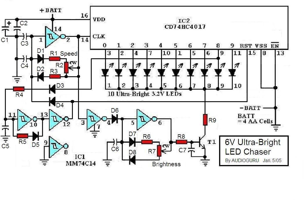
This project involves a sequence of Ultra-Bright LEDs that light up briefly in a circular pattern, mounted on a CD. The LEDs flash for 15 milliseconds, followed by a one-second pause, creating a visually appealing effect. The brief flashes...
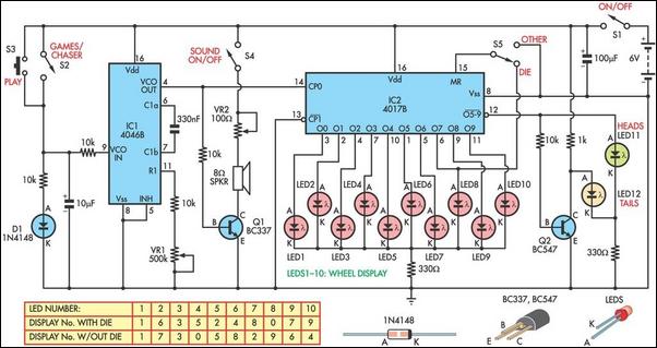
This circuit functions as a light chaser and can be configured to simulate either a heads or tails game (Two Up) or a dice game. It incorporates a speaker to replicate the sound of a spinning roulette wheel. The...
The schematic for the LED lighting circuit in a refrigerator consists of eight high-brightness white LED lights. These LEDs are housed in a transparent white plastic tube, which is the same height as the refrigerator cabinet. The circuit receives...
The safe 12V car adapter described here can be used to limit the current from a +12 volt car battery, available from the in-dash cigar lighter power port, to below 2.6A. The 12V car adapter is designed to ensure that...
The 555 Astable generates a clock for this circuit, functioning as an oscillator that produces a square wave output at pin 3. This output is counted by the CD4017 decade counter, which creates a running lights effect. The CD4017...
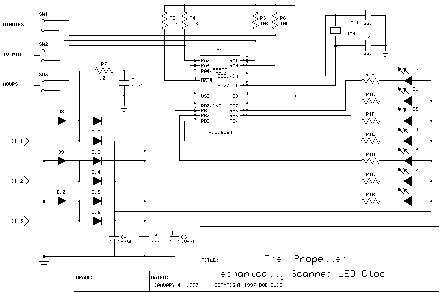
A motor spins the "propeller", and a small microprocessor keeps track of time and changes the pattern on seven LEDs with exact timing to simulate a 7 by 30 array of LEDs. It is an illusion, but it works...