
voltage How can I make LEDs light up equally

In this circuit, three binary switches are employed to represent values ranging from 0 to 7 (000 to 111 in binary). Each unique combination of the switches will activate a specific number of light-emitting diodes (LEDs) corresponding to the binary value represented by the switches. The challenge lies in ensuring that all LEDs receive an equal amount of current and voltage, which is essential for achieving uniform brightness across all activated LEDs.
To achieve this, a current-limiting resistor must be placed in series with each LED to prevent excessive current from flowing through them, which can lead to uneven brightness and potential damage. The value of this resistor can be calculated using Ohm's Law (V = IR), where V is the voltage drop across the LED, I is the desired current through the LED, and R is the resistance. The forward voltage drop of the LED, typically around 2V for standard red LEDs, should be considered when calculating the resistor value.
Additionally, a common approach to ensure that the LEDs light up with equal intensity is to use a constant current source. This can be achieved with a simple transistor-based circuit or a dedicated LED driver IC that regulates the current flowing through the LEDs, regardless of the number of LEDs activated.
In the proposed design, when a switch is closed, it completes a circuit that allows current to flow through the corresponding LED(s) and their associated resistors. The arrangement should ensure that no more than three LEDs are lit at any one time, which simplifies the design of the current-limiting resistors.
It is also advisable to use a microcontroller or a logic circuit to interpret the switch states and control the LEDs accordingly. This approach allows for more flexibility in managing the LED states and can help to simplify the circuitry by centralizing the control logic.
In summary, the successful implementation of this circuit requires careful consideration of the electrical characteristics of the LEDs, the use of current-limiting resistors, and possibly the integration of a constant current source to maintain uniform brightness across all LEDs, regardless of the binary combination represented by the switches.There are three switches that represent "binary number", and according to that switches` combination, number of lit LEDs change to represent that binary number. I am wondering how do provide equal current and voltage for LEDs and make them light up with equal luminous intensity independent of switches` combination.
Probably I`m not understanding s ome major law in electronics. 🔗 External reference
Related Circuits
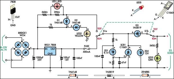
This 8V DC power supply is designed for use with high-end electronic equipment. It includes full over-voltage protection to safeguard against regulator failure, whether in the supply itself or in the connected device. The circuit employs a standard full-wave...
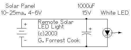
The remote solar powered LED light takes advantage of the current limited nature of solar photovoltaic cells. If light shines on the solar array, current will flow through the circuit. For a typical size of solar cell, there is...
This circuit utilizes a 555 timer configured to operate in astable mode. This setup generates a continuous output through Pin 3 in the form of a square wave. When the timer's output transitions to a high state, it triggers...
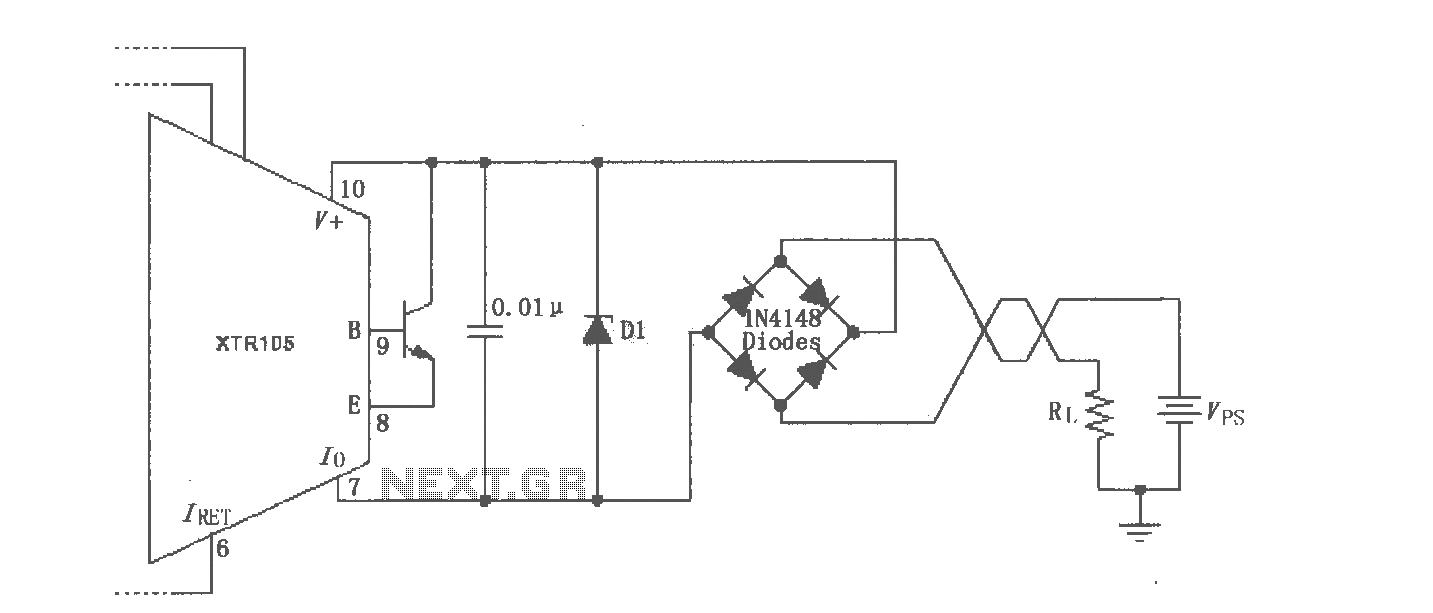
The XTR105 reverse voltage and over-voltage surge protection circuit is illustrated. A Zener diode rated at 36V can be utilized, with options including 1N4753A or 1N6286A. The maximum supply voltage (Vps) should be less than the minimum breakdown voltage...

This is the schematic of the conventional light dimmer. L1 and C2, C3 form the lichtnetontstoring. In this circuit meets almost every TRIAC as a TIC226D. For C1, C2 and C3 good capacitors (MKT example) with a minimum operating...
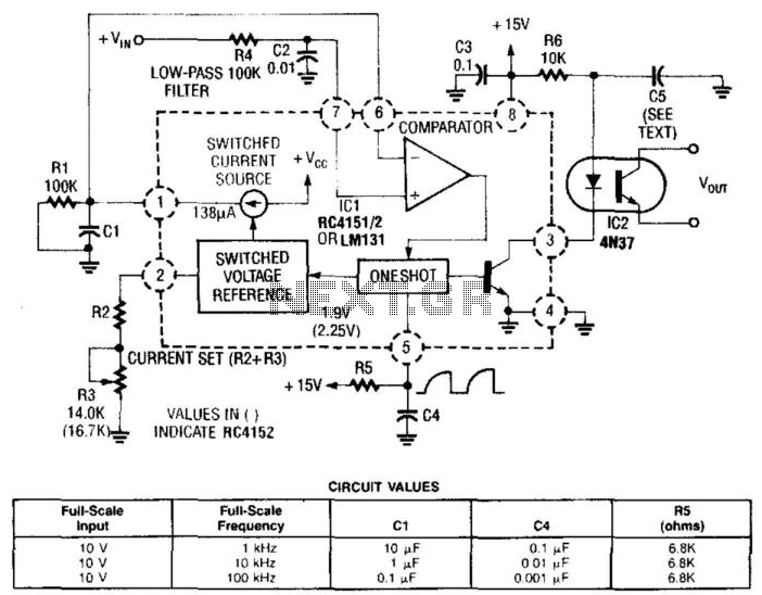
In this circuit, a Raytheon RC4151 or National LM131 is utilized alongside an optocoupler for applications where input-to-output isolation is desirable. Circuit values are indicated in the figure for various applications. The circuit employs a Raytheon RC4151 or National LM131,...