
led chaser provides three game

This circuit design integrates several essential components to create an engaging and interactive gaming experience. The 4046 PLL not only serves as a clock generator but also allows for precise control over the frequency of the output signal, which is critical for the visual effects produced by the chaser LEDs. The 4017 decade counter effectively counts the pulses from the VCO, enabling the sequential illumination of the LEDs in a chaser pattern, which can be visually appealing and captivating for users.
The circuit's versatility is highlighted by its ability to switch between different game modes. The use of switches S2, S3, and S5 allows users to easily transition between the roulette and dice functionalities. The design also accommodates user preferences by enabling the removal of certain features, thus tailoring the gameplay experience. The adjustable potentiometer VR1 provides further customization, allowing users to set the speed of the chaser LEDs according to their liking.
Sound integration is achieved through the use of the speaker driven by transistor Q1. The sound effects enhance the gaming experience, simulating the ambiance of a casino environment. The inclusion of trimpot VR2 for sound level adjustment ensures that the audio output can be tailored to suit different settings, whether for quiet play or a more immersive experience.
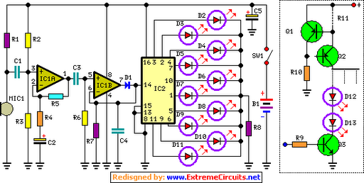
Overall, this circuit represents a well-thought-out design that combines visual and auditory elements to create a fun and engaging device suitable for various gaming scenarios. The thoughtful arrangement of components and the ability to customize features make it a versatile platform for entertainment.This circuit is essentially a light chaser but it can also be set to provides heads or tails (Two Up) or a Dice (die). It also has a speaker to simulate the sound of a spinning roulette wheel. Note that the dice and heads/tails features can be deleted if required and rules for the games created to suit individuals; eg, betting can be used or the n
umbers recorded and then totalled to get the highest score per game. IC1 is a 4046 phase locked loop (PLL) but only the voltage controlled oscillator (VCO) portion of the chip is used to provide the clock pulse for IC2, a 4017 decade counter/divider. In roulette wheel mode, switch S3 is pushed to start the game. This charges the 10 F capacitor at pin 9 and as the capacitor discharges, the output frequency is slowly reduced to slow the rate of the chaser LEDs driven by IC2.
In chaser mode, switch S2 is closed to provide a fixed frequency output from IC1. This can be varied over a wide range with potentiometer VR1. Transistor Q1 is also driven by the oscillator output of IC1 and it drives the speaker. Trimpot VR2 varies the sound level while switch S4 turns it off. Switch S5 selects Die or other (chaser/roulette). In Die mode, pin 6 is connected to the reset, pin 15, so that the circuit only counts to 6 whereas in the other modes it counts to 10 and displays all LEDs. Pin 12 drives transistor Q2 and two LEDs to provide the Heads/Tails function. 🔗 External reference
Related Circuits
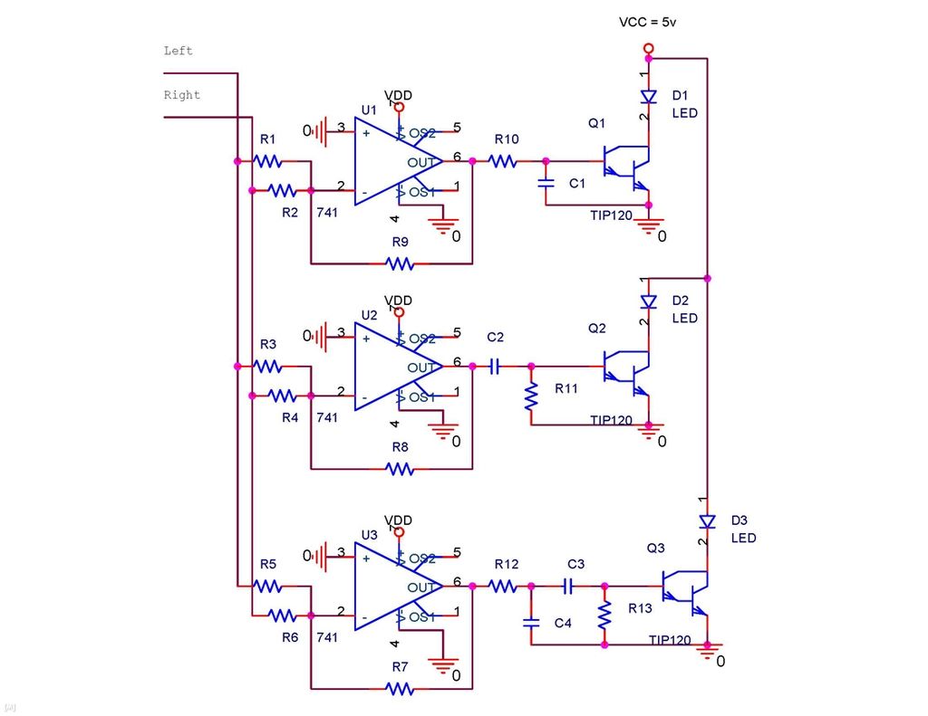
The basic circuit illuminates up to ten LEDs in sequence, following the rhythm of music or speech picked up by a small microphone. The expanded version can drive up to ten strips, each formed by up to five LEDs,...
The lower the voltage, the easier it would be to fit the batteries into the caboose along with the flasher circuit. The venerable LM3909 LED flasher came to mind, but when it flashed, the LED only emitted a tiny...

This Outdoor LED Solar Garden Lights project is a hobby circuit for an automatic garden light that utilizes a light-dependent resistor (LDR) and a 6V/5W solar panel. During daytime, the internal rechargeable 6 Volt sealed lead-acid (SLA) battery is...
It is possible to synchronize the LEDs so that the speakers continue to play loudly while the LEDs are not always illuminated during music playback. The individual has a solid understanding of electrical concepts and is seeking a method...
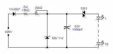
This circuit will flash a string of LEDs, typically 16, with direct connection to the mains and with a period adjustable between 1 and 4 seconds depending on the setting of the 22K/1W pot. Operation at 110V should also...
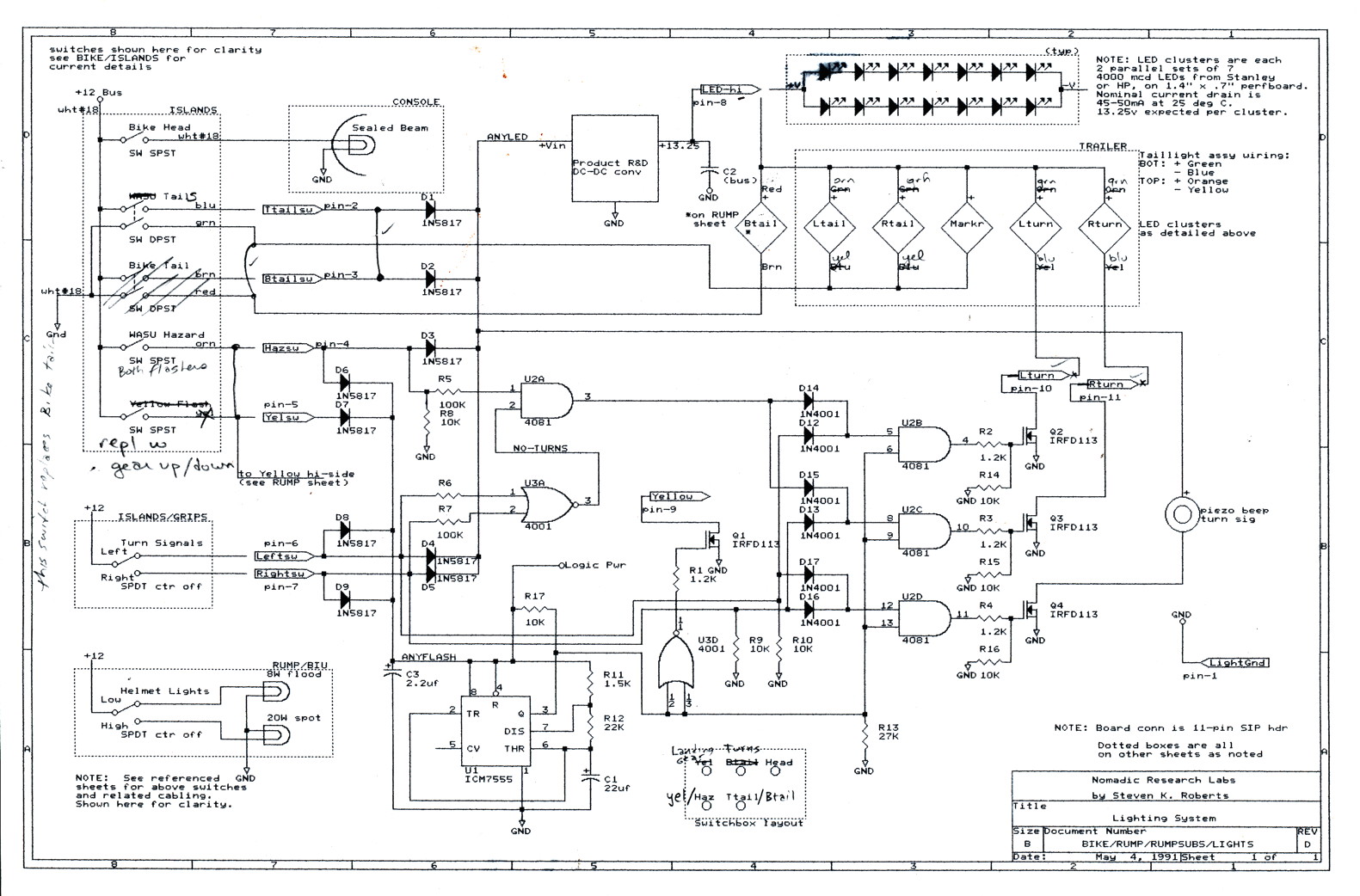
This second issue of the Bikelab Notes, published during the development of BEHEMOTH at Sun Microsystems, focuses on high-brightness LED taillight assemblies that were not commercially available at the time, making this a unique project. The author also comments...