
LED Counter with IC 4017

The circuit utilizes the 4017 decade counter IC, which is designed to sequentially activate its 10 output pins in response to clock pulses. Each output corresponds to a specific count, and once the count reaches 10, the sequence resets to output 0. The primary clock signal for the 4017 is generated using a NAND gate configuration from the CD4093, which serves as an oscillator. The frequency of this clock signal can be adjusted using a variable resistor (VR), allowing the output activation cycle to be set to 1 second.
The arrangement of the circuit involves connecting the output pins of the 4017 to individual LEDs, each corresponding to the outputs from 0 to 9. Each LED will illuminate sequentially with each clock pulse, creating a visual indication of the counting process. The circuit will continue to cycle through the outputs indefinitely until power is removed.
To ensure proper operation, it is essential to ground the unused pins of the NAND gates in the CD4093. Specifically, pins 5, 6, 8, 9, 12, and 13 should be connected to ground to prevent floating inputs, which could lead to erratic behavior or noise in the circuit. This grounding stabilizes the NAND gate operation and ensures reliable clock pulse generation.
Overall, this basic configuration serves as an effective demonstration of sequential output control using a decade counter and provides a practical application for visual indicators through LED activation.The circuit presented this month is a basic configuration of the very versatile 4017 IC Chip. In the most common use of the IC, it will turn on 10 separate outputs sequentially. Typically, the circuit is used to turn on a LED for certain time cycle. In the circuit shown the VR can be adjusted so that the clock output of the NAND gate will be 1 second. With this clock at 1 second intervals, the 4017 chip will turn on output # 0 to be high which will light and LED.
When clock pulse 2 is received a second later, output #1 will go high which will turn on LED2. This process will continue until all 10 outputs have gone on and then it will start all over again until you turn the power off. When building this circuit you should tie the left over pins of the other NAND gates in the CD4093 to ground.
Therefore, pins 5,6,8,9, 12 and 13 should be connected to ground. 🔗 External reference
Related Circuits

This discussion focuses on headlamp dimmer-controlled fog lamps within the Ford Raptor Lighting Modifications Forum, part of the Ford Raptor Forums - Modifications category. For those interested in installing fog lamps that can be controlled by the dimmer switch...
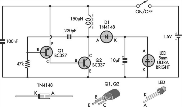
This simple LED torch is powered by a 2-transistor blocking oscillator that increases the voltage from a 1.5V cell. The design utilizes the natural current limiting characteristics of a 150 µH choke to prevent the white LED from being...
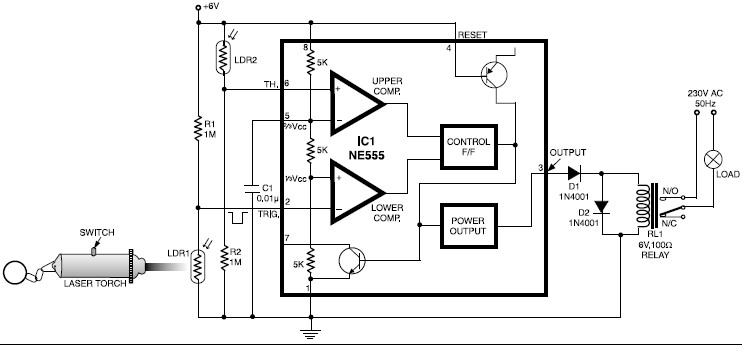
This circuit is designed around a 555 timer and utilizes a minimal number of components. Its simplicity allows even beginners to easily assemble and operate it as a control device. A readily available laser pointer can be used to...

This voltage booster circuit for driving one or more white LEDs utilizes a 555 timer as its main component. The timer, designated as IC1, operates as a resettable astable multivibrator with R1, R2, and C2 serving as the timing...
This temporary lamp circuit is very useful in emergency situations or in any application where there is limited time to turn off the lamp. Just press the switch to activate. The temporary lamp circuit is designed to provide immediate illumination...
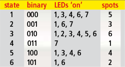
Every DIY enthusiast creates their own electronic dice using LEDs as indicators. This eliminates the need to physically throw the dice; instead, a button press activates the roll. The circuit design ensures fairness by preventing manipulation of the outcome,...