
LED Crystal Tester

The described circuit comprises an oscillator utilizing a 2N3563 transistor (Q1) which is critical for generating oscillations when a compatible crystal is connected. The oscillator’s output is processed through a 1N4148 diode (D1) for rectification, ensuring that the AC signal is converted to a usable DC voltage. This voltage is then smoothed by a 100pF capacitor (C3), which filters out any voltage fluctuations, providing a stable signal to the base of the second transistor (Q2), also a 2N3563.
When Q2 is activated by the voltage from C3, it allows current to flow through an ultra-bright red LED (D2), which visually indicates the functionality of the crystal. The circuit is designed such that only a properly functioning crystal will enable oscillation, thus illuminating the LED as a confirmation of the crystal's integrity.
The circuit's resistor configuration includes R1 (100K), R2 (2.2K), and R3 (330 Ohm), where R3 can be adjusted to lower values (220 or 270 Ohm) to accommodate applications involving higher frequency crystals. This adjustment can affect the brightness of the LED, potentially resulting in a dim glow for certain crystal types.
Powering the circuit is a standard 9-volt battery, with an optional momentary SPST push-button switch (S1) included to extend battery life during testing. The circuit may also utilize crocodile clips or similar connectors for attaching the crystal under test, enhancing usability.
The complete parts list includes capacitors (C1, C2 at 220pF and C4 at 0.1uF), the specified transistors (Q1, Q2 as 2N3563), and the signal diode (D1), ensuring that all components are suitable for the intended operation of the oscillator circuit. This design is particularly effective for testing crystals operating in higher MHz ranges, making it a valuable tool for electronics testing and troubleshooting. Transistor Q1, a 2N3563, and its associated components form an oscillator circuit that will oscillate if, and only if, a good crystal is connected to the test clips. The output from the oscillator is then rectified by the 1N4148 signal diode and filtered by C3, a 100pF capacitor.
The positive voltage developed across the capacitor is applied to the base of Q2, another 2N3563, causing it to conduct. When that happens, current flows through Led1, causing it to glow. Since only a good crystal will oscillate, a glowing LED indicates that the crystal is indeed OK. You can use the NTE123AP, PN100, or the 2N3904, for the transistors, however, the circuit works better with the 2N3563's for crystals in the higher MHz.
The NTE108 is a direct replacement for the 2N3563. R3, the 330 ohm resistor for the Led, can be lowered to 220/270 ohm if your application is for crystals in the high MHz, which makes the led glow dimly in some instances. The circuit is powered by a standard 9-volt battery and the SPST push button power-switch is included to prolong battery life but not really needed if you use a socket for the crystal-under-test. I'm using this particular simle tester myself. Parts List: R1 = 100K C1,C2 = 220pF R2 = 2K2 C3 = 100pF R3 = 330 Ohm C4 = 0.1uF (100 nF) Q1,Q2 = 2N3563 D2 = red led, ultra-bright D1 = 1N4148 S1 = Momentary Push-button, SPST (optional) Miscellaneous: crocodile clips (or others), 9V battery clip, wire, solder, etc
🔗 External reference
Related Circuits
The following touch switch circuit utilizes a CA3240 dual BiMOS operational amplifier to detect small currents flowing between the contact points on a touch plate. The touch switch circuit employs a CA3240 dual BiMOS op-amp, which is known for...
Microdot - wrist watch LED pattern timepiece. This project is a circuit board designed for creating a wristwatch-sized version. The Microdot wristwatch project involves the design and implementation of a compact circuit board that integrates LED technology to display time...
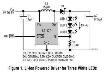
The LT1937 is a step-up DC/DC converter specifically designed to drive white LEDs with a constant current. The device can drive two, three or four LEDs in series from a Li-Ion cell. Series connection of the LEDs provides identical...
This circuit illustrates a Go-No/Go Tester Circuit utilizing a 555 Timer IC. Features include a more advanced unit with a precise timed testing procedure. The Go-No/Go Tester Circuit is designed to evaluate components or assemblies by providing a simple pass/fail...
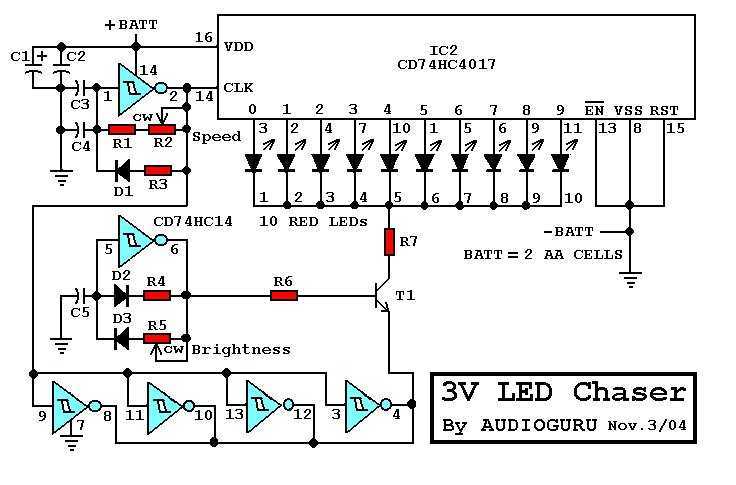
There are many 9V chaser circuits that seem to waste about 7V when driving LEDs that are only about 2V. This project is unique, because it uses only two inexpensive alkaline battery cells totaling 3V for power. Since most...
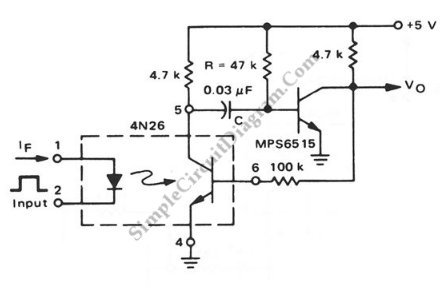
This is a pulse stretcher circuit utilizing an optocoupler. The circuit employs a 4N26 optocoupler in conjunction with a standard one-shot circuitry. The pulse stretcher circuit is designed to elongate the duration of an incoming pulse signal, which is particularly...