
LED Dance Pad

The DDR pad design leverages a unique approach to user interaction by employing LEDs not just for lighting but also for sensing foot placement. The absence of mechanical components minimizes wear and tear, enhancing durability and maintenance. The system architecture consists of a master controller interfacing with multiple slave controllers, which allows for a distributed processing approach. Each slave controller is tasked with monitoring its designated set of LEDs, providing real-time feedback based on user interaction.
The sensing mechanism operates on the principle of capacitive discharge, where the sensing LED's capacitance is charged and subsequently discharged based on light reflectance from the user's foot. This method provides a reliable and responsive means of detecting foot placement without the need for mechanical switches. The master controller aggregates data from the slaves and interprets it to determine the state of each arrow, allowing for seamless interaction with the gaming system.
The physical construction of the DDR pad emphasizes stability and usability. The choice of materials, including plywood and 2x4 lumber, ensures a robust structure capable of withstanding repeated use. The design includes thoughtful considerations for wiring and cable management, allowing for a clean and organized setup. The incorporation of drilled holes facilitates easy routing of power and communication lines, contributing to the overall aesthetic and functionality of the pad.
Finally, the finishing touches, such as the application of primer paint, not only enhance the visual appeal of the pad but also provide a protective layer against environmental factors, ensuring longevity. Overall, this innovative DDR pad design represents a significant advancement in interactive gaming technology, combining aesthetic design with functional engineering.Using LEDs as light sensors. A DDR pad. We designed our pad to have no moving parts. Instead, we chose to measure light reflectance off the user`s feet to determine if one of the arrows was being stepped on or not. Since a design with no moving parts offers little to no tactile feedback, we wanted to make sure the pad offered some other form of feedback, so the user would know when they
had successfully stepped on the arrow. The design consists of one master controller and four slave controllers. Each slave controls a set of 15 LEDs. Thirteen LEDs are placed around the border of the arrow and flash in rhythm with the music. The remaining two LEDs are used as an illumination and sensing pair - the LED pointing straight up acts as a permanent flashlight, and the LED at an angle serves to sense reflection of the previous LED off the foot of the player. Readings are taken with the technique described in the MERL paper, summarized here. We place the interior sensing LED in reverse bias mode to allow the LED to charge up a capacitance in the LED junction itself.
When a reading is to be taken, we set the cathode to input mode, disable the internal pull-up resistor, and time how long it takes the capacitance to discharge. Greater light input results in a shorter discharge time. As light from the illumination LED reflects off the foot of the player, the time the LED takes to discharge through the microcontroller decreases.
By comparing this time to a threshold, the slaves determine if the arrow is pressed, and will raise or lower a line to the master accordingly. The master runs the main DDR pad controller program. It determines when the arrow LEDs should be on by and receives constant readings from the slaves. The master passes the readings from the slaves on to the Xbox 360 controller. The master can receive lighting commands from Stepmania running on a computer through a USB serial port, or it can just leech power from an Xbox 360.
The frame of the DDR pad was built using plywood and 2x4 pieces of wood to divide the pad into 9 equal squares in a 3x3 fashion. The bottom of the pad is a piece of plywood cut to 33"x33". The left and right edges were constructed using 33" pieces of 2x4 laid on their narrow side. The upper and bottom edges and the two horizontal dividing pieces were constructed with 30" pieces of 2x4 on their thin sides, so that they fit within the left and right edges.
The vertical dividing pieces were constructed as 6 10" pieces of 2x4 on their thin sides to fit within the horizontal dividers. The 2x4 pieces of wood are screwed together at every meeting point and screwed into the plywood from the bottom.
The four pieces that create the middle square had holes drilled in them before being screwed in, so that wires could pass underneath the 2x4. Similar treatment was given to the two horizontal dividing pieces of the top left and top right squares.
1" circular holes were drilled in the upper edge in the center of the top left and top right squares so communication and power cables could be run to the pad. After all holes were drilled and all the pieces were screwed together, the frame as a whole was spray painted with one coat of prime
🔗 External reference
Related Circuits
The LED Torch is based on a 7555 timer running in astable mode (do not use an ordinary 555). A white LED (Maplin order code NR73) produces 400 mcd light output, which, when focussed, can illuminate objects at 30...
It is widely believed that light can be beneficial for human skin and mental well-being. Light at specific wavelengths may also help alleviate depression and allergies. Numerous products are available on the market, priced from a few tens of...
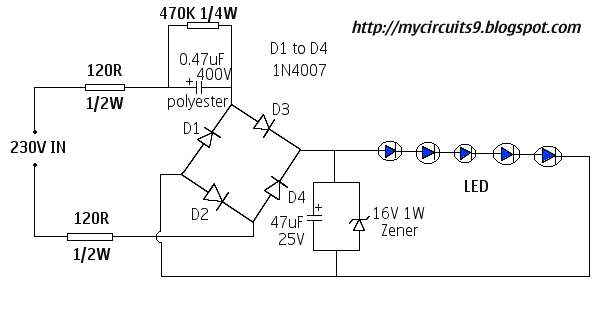
This document presents a 230V LED driver circuit that operates without a transformer. The circuit utilizes five LEDs, although the number can be increased as desired. The absence of transformers significantly reduces both the cost and size of the...
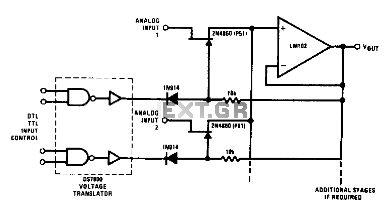
This analog switch utilizes the 2N4860 JFET, which features a low on-resistance of 25 ohms and minimal leakage current. The LM102 is employed as a voltage buffer in the circuit. Additionally, this configuration can be modified for use in...
This high power led mood light is based on PIC16F628 and the ability of this mcu to produce PWM pulses. Varying pulse width we can produce millions of color combinations using only the three basic colors. So only one...
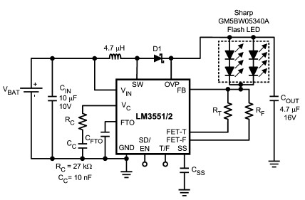
The LM3551 and LM3552 are fixed frequency, current mode step-up DC-DC converters featuring two integrated NFETs. These devices facilitate the design of a straightforward and highly precise LED brightness control system. They are capable of driving loads up to...