
LED Dice schematic

The circuit design for this dice simulation project incorporates a microcontroller, which serves as the central processing unit for managing the LED outputs and controlling the timing of the flashing sequence. The microcontroller is programmed to respond to input from a touch-sensitive plate, which acts as the trigger for the dice simulation.
Upon activation, the microcontroller initiates a rapid sequence of LED flashes. The seven LEDs are arranged to correspond to the traditional spots found on a standard six-sided die, with an additional LED to indicate the zero value or a "roll" state. The flashing pattern is designed to emulate the randomness of a dice roll, creating a visually engaging experience.
To enhance the realism of the simulation, the microcontroller implements a gradual deceleration algorithm. As the user continues to touch the plate, the flashing of the LEDs begins at a high frequency, mimicking the rapid rolling of a die. After a predetermined period, the frequency of the flashes decreases, simulating the slowing motion of a die coming to rest. Eventually, one LED lights up to indicate the final outcome of the roll, corresponding to the number displayed on an actual die.
The circuit may also include a resistor network to limit the current through the LEDs, ensuring they operate within safe parameters. Additionally, a capacitor may be employed to smooth out the power supply to the microcontroller, providing stable operation during the flashing sequence.
Overall, this project not only serves as an entertaining game but also provides an excellent platform for learning about microcontroller programming, LED control, and circuit design principles.This project has two advantages over previous dice circuits. It produces a realistic readout as well as a `slow-down` feature. These combine to make it one of our most popular games projects. As can been seen in the photo, the 7 LEDs are positioned on the board in the same positions as the spots on a dice (die). When these are activated, they simulate the rolling of a real dice as it rolls across the table. The way the circuit works is very ingenious. When you touch the TOUCH PLATE wires, the LEDs start flashing in a similar manner to a dice rolling over and over. This gradually slows down to rest and a number is displayed exactly like the spots on a dice. 🔗 External reference
Related Circuits

Efficient automatic solar garden lights circuit with minimal components. The advantage is that it operates completely automatically, with the solar panel serving as a light detector. The efficient automatic solar garden lights circuit is designed to provide illumination using renewable...

This is a programmable clock timer circuit that utilizes individual LEDs to indicate hours and minutes. Twelve LEDs are arranged in a circle to represent the 12 hours of a clock face, while an additional 12 LEDs are positioned...
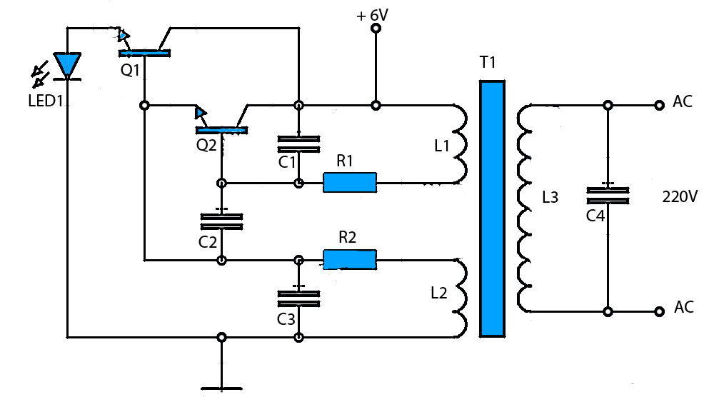
6V to 220V Inverter Schematic. Starting from a 6-Volt input on the DC current to produce a 220-Volt AC output. The inverter circuit converts a low voltage DC input, specifically 6 volts, into a high voltage AC output of 220...
Electronic potentiometer using a standard CMOS logic and analog multiplexers. Pot have low distortion (0.005% less at 1 V rms) and is it easy for beginners to understand. In the beginning, the art of Hi-Fi, in the absence of...
This is a resonant mode LED driver circuit. This circuit is designed to provide a constant DC current through a specified number of LEDs. The resonant mode LED driver circuit operates by utilizing resonant inductive elements to achieve efficient energy...
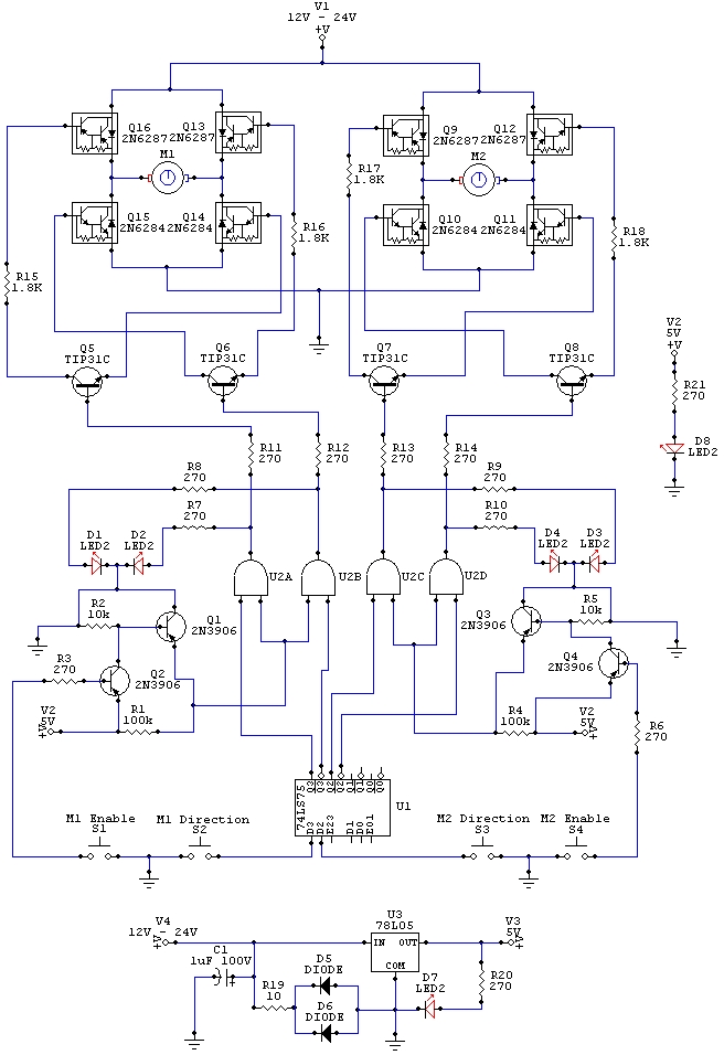
The wiring schematic played a significant role in the robot. This diagram is used to graphically display all the wiring of the motor-controlling micro-components that enabled the robot to physically move forward, backward, left, right, and stop. This diagram...