
Resonant Mode LED Driver

The resonant mode LED driver circuit operates by utilizing resonant inductive elements to achieve efficient energy transfer while maintaining a stable output current. The primary components of this circuit typically include a resonant inductor, a switching device (such as a MOSFET), and a control circuit that regulates the switching frequency to match the resonant frequency of the inductor-capacitor (LC) tank circuit.
The operation begins with the control circuit initiating the switching of the MOSFET, which allows current to flow through the resonant inductor. As the current builds up, the energy is stored in the inductor until the switch turns off, causing the inductor to release its energy to the LED string. The resonant frequency is critical as it determines the efficiency and effectiveness of energy transfer. By carefully selecting the values of the inductor and capacitor, the circuit can be tuned to minimize losses and maximize the output current delivered to the LEDs.
Additionally, feedback mechanisms are often incorporated to monitor the output current and adjust the duty cycle of the switching device accordingly. This ensures that the LED string receives a constant current, regardless of variations in input voltage or load conditions. The design may also include protection features such as overcurrent protection and thermal management to safeguard the components and enhance the reliability of the circuit.
Overall, the resonant mode LED driver circuit is an efficient solution for driving LED strings, providing not only constant current but also improved energy efficiency compared to traditional linear or switch-mode drivers. This makes it suitable for a variety of applications where consistent LED performance is critical.This is Resonant Mode LED Driver circuit. This circuit is used to give a constant DC current through a string of a given number of LEDs. This circuit uses. 🔗 External reference
Related Circuits

The Allegro A8732 is a Xenon photoflash charger integrated circuit (IC) specifically designed for ultra-low power, compact cameras, especially in mobile devices such as camera phones. It utilizes primary-side voltage sensing, which eliminates the need for a secondary-side resistive...

The gain controller utilizes a 4066 quad bilateral switch to electronically select a feedback resistor for the 741 operational amplifier. One or more switches can be activated simultaneously to achieve a stepped, variable-gain range from less than 1 to...
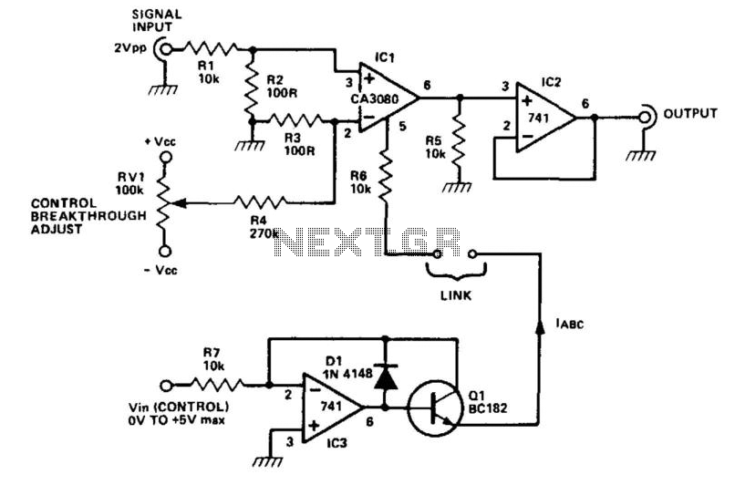
The CA3080 can be utilized as a gain-controlling device. The input signal is attenuated by resistors R1 and R2 so that a 20 mV peak-to-peak signal is applied to the input terminals. If this voltage exceeds a certain threshold,...
This circuit is designed to drive a total of 42 LEDs, assuming a forward voltage of approximately 2.2V per LED and a forward current of around 21mA for adequate brightness. If the specifications of the LEDs differ significantly, modifications...

The audio mixer schematic proposed is developed around four amplifiers built inside the SSM2024 produced by Precision Monolithics Inc. (PMI) and is voltage-controlled (VR). The maximum VR voltage is 5.5 volts. The signal-to-noise ratio is 90 dB, and the...
A good way to mount the circuit board is to use a hot glue gun to mold the circuit underneath the lamp housing. There is plenty of space there for your board. At the next photos you can see...