
Automatic interval timer circuit composed of PUT

The circuit utilizes a Programmable Unijunction Transistor (PUT) as the primary oscillating component, which is known for its precise timing capabilities. The PUT is configured to generate a square wave output that can be used for various timing applications. The automatic interval timer circuit is designed to allow users to select between two modes of operation through the use of a single-pole double-throw (SPDT) switch, S1.
In automatic timing mode 1, the circuit is set to provide a predetermined time interval for automatic operations, such as activating a relay or controlling a motor. This mode is particularly useful in applications that require repetitive actions without user intervention. The timing duration can be adjusted by varying the values of the timing components, including resistors and capacitors in the circuit.
In contrast, the interval timing mode allows for manual control over the timing intervals. This mode is activated when S1 is switched to position 2. In this configuration, the circuit can be used for applications where precise control over timing is essential, such as in pulse generation or signal modulation.
The component RP2 plays a critical role in the circuit's operation. It is a variable resistor that allows for fine-tuning of the timing intervals. If the resistance value of RP2 is too large, it can limit the anode current flowing into the PUT, potentially causing the oscillator to fail to operate correctly. This highlights the importance of selecting appropriate resistance values to ensure reliable circuit performance.
Overall, this circuit design demonstrates versatility in timing applications, allowing users to switch between automatic and manual modes efficiently. Proper understanding and adjustment of the circuit components are essential for achieving the desired timing characteristics in various electronic applications.Figure 1 is composed of the PUT and other automatic interval timer circuit. In the circuit, PUT is the oscillator. Using the switch S1 to switchover the interval time and automatic time. When S1 connects to 1, it is automatic timing mode 1, thenS1connects to2, itis the interval time. If the resistance of RP2is too large, PUT anode current is less than the.. 🔗 External reference
Related Circuits

Retired Physics Professor Steven E. Jones is working on a simple overunity circuit that he has observed achieving up to 20 times overunity. This circuit is a variation of the Joule Thief or a blocking oscillator. His design incorporates...
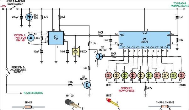
Do you drive an older car without an automatic "lights-on" warning circuit? If so, you have likely accidentally left the lights on and drained the battery on one or more occasions. This headlights reminder circuit will prevent that issue....
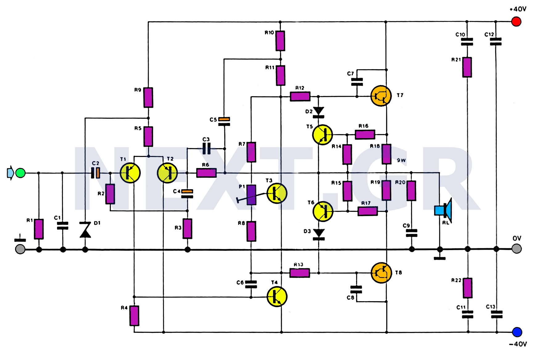
This amplifier is designed with the following specifications: distortion less than 0.1% at full power of 100W even at 20KHz, with power attributed to an extended bandwidth. The output transistors are protected against short circuits, and the power supply...
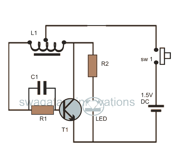
This post discusses blue and white LED drivers utilizing a joule thief circuit. Further exploration of the circuit's functionality is provided, along with simulation points. The joule thief circuit is a simple and efficient boost converter that allows for the...
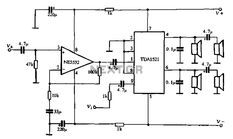
Active speaker with amplifier circuit TDA1521 and NE5532, featuring dual-channel input and dual-channel output. The active speaker circuit utilizes the TDA1521 integrated circuit, which serves as the power amplifier. This IC is designed for high-efficiency amplification, providing a robust output suitable...
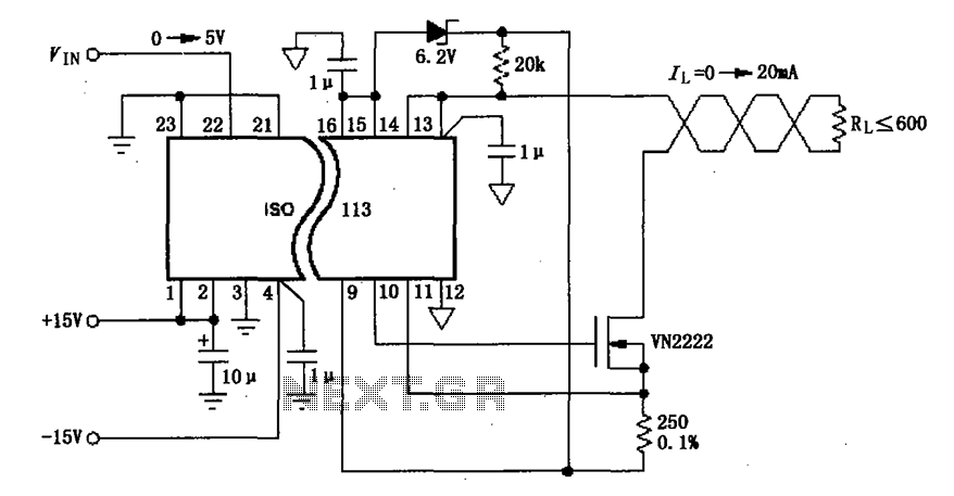
The circuit depicted in the figure consists of an ISO113 current loop isolation drive circuit that operates with an input signal (VIN) to provide an isolated amplified output of 0 to 20 mA. This current is transmitted to the...