
led discharge circuit

The described circuit serves as an educational platform for understanding key electronic concepts and components. It incorporates Pulse Width Modulation (PWM) for controlling the power delivered to devices, enabling the simulation of varying output levels. Digital-to-analog conversion allows for the transformation of digital signals into analog voltages, which is essential for interfacing with analog components. The inclusion of RC filters aids in smoothing out signals, while charge and discharge curves provide insights into the behavior of capacitors in a circuit.
The use of an ATmega microcontroller enhances the circuit's functionality, offering programmable control over the output pins. This allows users to manipulate the circuit's behavior through software, facilitating experiments with timing and signal generation. The ATmega's capability to read analog inputs enables real-time monitoring of circuit parameters, such as voltage levels or signal waveforms, thereby improving the understanding of circuit dynamics.
For practical implementation, the circuit can be constructed on a breadboard, utilizing standard components such as resistors, capacitors, and the ATmega microcontroller. The schematic diagram, which can be created using CAD software like EAGLE, should clearly indicate the connections between components, including power supply, ground, and signal paths. Proper labeling of components and values is essential for accurate assembly and troubleshooting.
In summary, this circuit serves as a versatile educational tool, providing hands-on experience with fundamental electronic principles, while also allowing for the exploration of more advanced topics such as microcontroller programming and signal processing.It`s enough to explore PWM and digital-to-analog conversion, and it illustrates how you can create your very own electronics workbench to explore RC filters , charge curves, discharge curves, pulse generators, timers, and even create a very simple oscilloscope to understand what`s going on in a dynamic electronic circuit. The first thing I need to do is clear things up a bit. While that above picture is a fully functioning circuit, it`s pretty awkward to see exactly what is hooked up to what. Some of these components are polarized, so there`s in fact more to it than which wire goes where . First thing to notice, is that there`s a lot more info here, and it`s a lot more precise. The components use a standard notation, and their values are also indicated. Now, although it was a fun exercise for me to draw this by hand and scan it in, it`s a bit tedious if I make mistakes while drawing or when things change.
Fortunately, there are computer-aided design ( CAD ) software packages which make it simple to draw and edit such schematics on-screen. Here`s the same schematic using EAGLE : But this is where the fun starts. We could just hook up a battery to it (+ to VIN and to GND), and there would in fact be some interesting behavior.
But we can do a lot better than that: we can put the entire circuit under computer control! The digital output pins on an ATmega are terrific controllable power sources, as long as we only need a few milliamps at 3. 3V or 5V. And if we need more well, that`s where transistors come in (to be described in a future post). The other great property of an ATmega (many MPUs, for that matter), is that they also have analog and digital inputs, so they can be used to measure various aspects of the circuit under test at the same time.
I still haven`t told you what the circuit does. But if you`ve played around a bit with this stuff before, you should be able to predict what this little sketch does: 🔗 External reference
Related Circuits
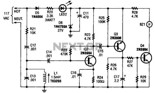
The baby-alert receiver consists of three transistors: Q2, configured as a high-gain linear amplifier; Q3, functioning as both an amplifier and detector; and Q4, which operates primarily as a switch. Additionally, there are several other components involved. The system...
With this circuit we can change the brightness of lamb, with a only key of touch. The key of touch is connected in the circuit, center of which is a special completed IC1, which is the S566B of SIEMENS....
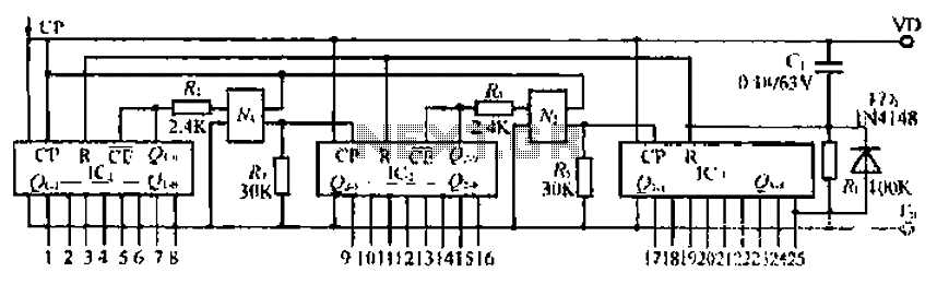
The CD4017B input signal is applied to the CP triggering pin. A pulse signal is sent through the IC, resulting in a straight-through output signal. The coupling device is used to control the input signal. When the power is...
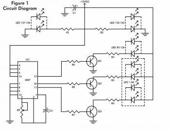
When power is applied to the circuit, all Red LEDs will flash on and off simultaneously. The Yellow LEDs will also flash, but only every other Yellow LED will be illuminated at any given time. The Green LEDs will...
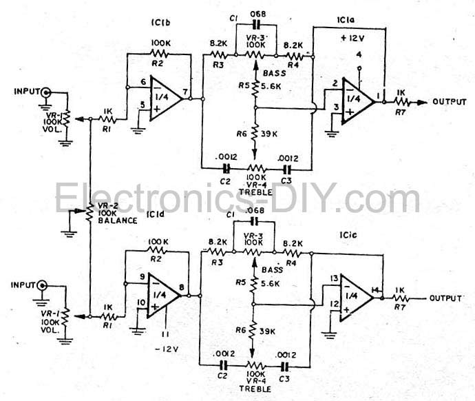
This simple tone control (bass and treble control) can be utilized in various audio applications. It can be integrated into amplifiers, function as a standalone control module, or even be incorporated into new and innovative instruments. The circuit employs...
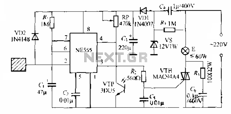
The circuit utilizes a NE553 automatic light sensor composed of 55 groups, allowing lights to turn on when individuals are present and turn off when they leave. The power supply includes VD1, vS, and C, with a 12V DC...