
Light circuit diagram: 1996 Ford Windstar Wiring Diagram

The wiring diagram for the 1996 Ford Windstar serves as a crucial reference for understanding the electrical layout and functionality of the vehicle's systems. It illustrates the power distribution network, which is essential for providing electrical energy to various components throughout the vehicle. The common connections section identifies shared wiring paths that facilitate communication and power transfer among different systems.
The rear circuit details are important for diagnosing and troubleshooting issues related to the rear lighting, audio systems, and any additional features located at the back of the vehicle. The ignition system wiring is vital for ensuring the proper operation of the engine start-up process, linking the ignition switch to the ignition coil and other critical components.
The fuse panel section is particularly important as it outlines the protective fuses that safeguard electrical circuits from overloads. Each fuse corresponds to a specific electrical component or system, and understanding this layout aids in quickly identifying and replacing blown fuses.
Battery connections are depicted to ensure proper installation and maintenance of the vehicle's power source, while the instrument illumination section provides insight into the wiring that controls dashboard lighting, enhancing visibility during night driving.
The radio wiring diagram is essential for audio system installation or repair, detailing the connections necessary for optimal sound performance. Additionally, the left rear speaker connections and the remote headphone module wiring are illustrated to facilitate the integration of audio components, enhancing the overall entertainment experience.
Solid-state components are represented in the diagram, indicating the use of modern electronic devices that offer improved reliability and performance over traditional mechanical components. Finally, the right rear circuit details are provided to complete the comprehensive overview of the vehicle's electrical system, ensuring that all areas are covered for effective maintenance and repair.The Part of 1996 Ford Windstar Wiring Diagram: power distribution, common, rear, ignition, fuse panel, battery, instrument illumination, radio, left rear speaker, remote headphone module, solid state, right rear 🔗 External reference
Related Circuits
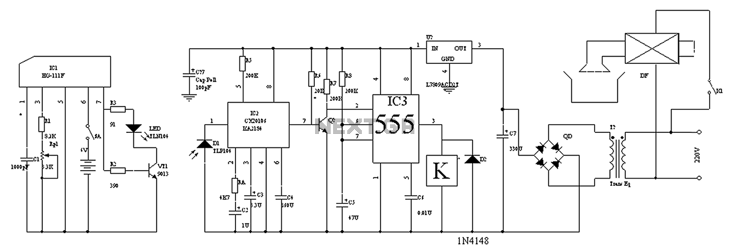
The circuit diagram for the automatic control of drinking fountains is presented below. The automatic control circuit for drinking fountains typically employs a combination of sensors and control elements to manage the operation of the fountain efficiently. The main components...
When light strikes the Light Dependent Resistor (LDR), its resistance decreases significantly. The voltage at the junction of the LDR and resistor R2 gradually charges capacitor C2 through resistor R1. After approximately 10 seconds, the voltage across the capacitor...
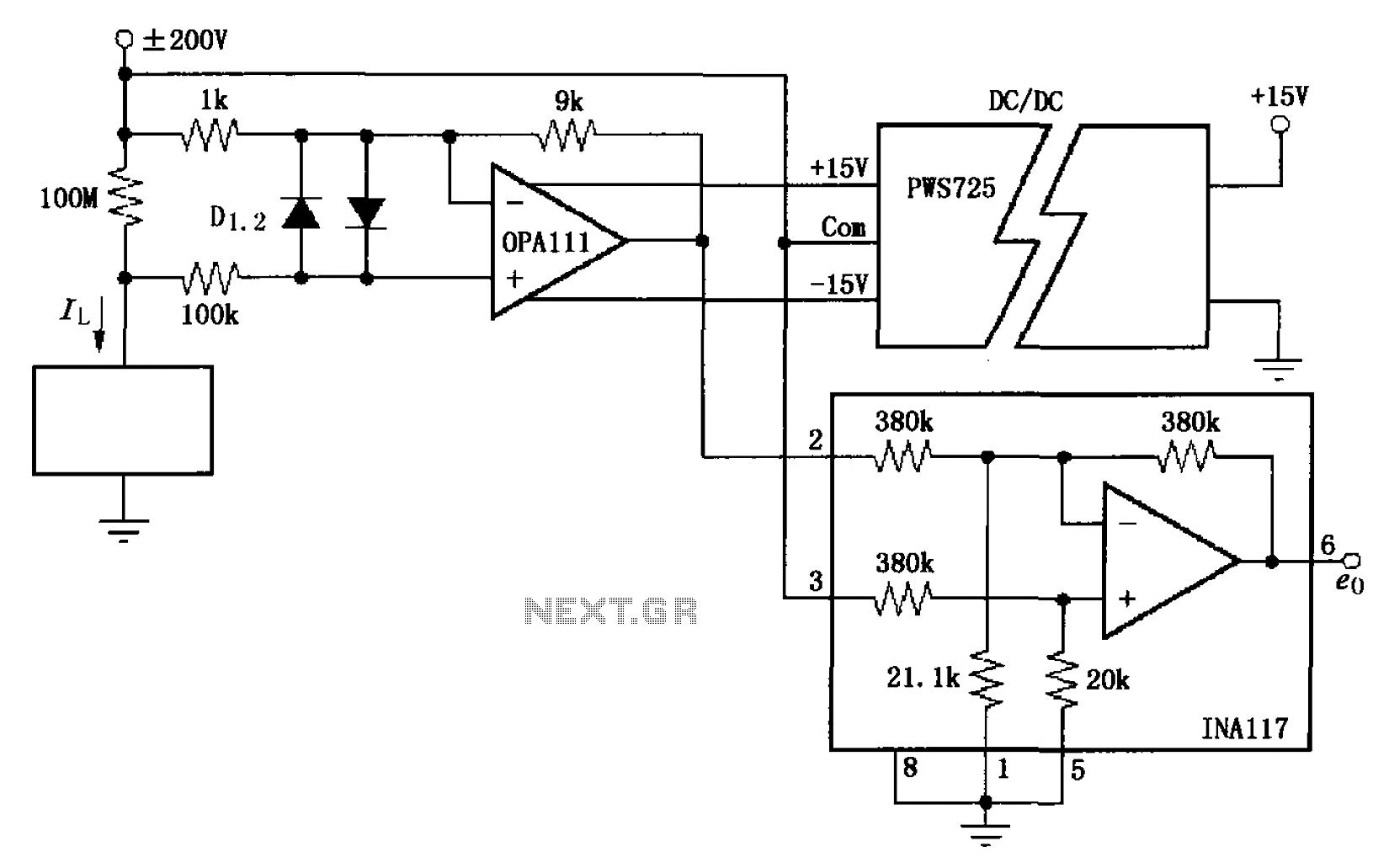
The circuit illustrated in FIG OPA111 is designed for measuring input buffer leakage current. The transistors D1 and D2, which are 2N3904 types, short the base and collector contacts while leaving the emitter open. When a power supply of...
This circuit is a soft light dimmer that utilizes the IGBT STGP10N50A and the TS555 timer as its primary components. The soft light dimmer circuit is designed to control the brightness of incandescent lamps or other resistive loads by...

This circuit has the advantage of transferring almost all the energy from the collapsing magnetic field of L2 to C2. In contrast, a typical Joule thief circuit allows some of this energy to return to the battery. This efficiency...
This circuitry facilitates the connection between the computer's Z RS-23 serial interface and the current ring circuitry. It converts the voltage signal of the transmission into a current signal of 20 mA, achieving a maximum speed of 1200 bits....