
LED Flasher Using Transistor

The LED flasher circuit operates using a basic timing mechanism, often implemented with a 555 timer IC configured in astable mode. In this configuration, the 555 timer generates a continuous square wave output, which can be used to drive the LEDs.
The circuit typically consists of the following components:
1. **555 Timer IC**: Serves as the core timing element, generating the ON and OFF signals.
2. **Resistors (R1, R2)**: These resistors set the charge and discharge times of the timing capacitor, thus determining the frequency of the oscillation.
3. **Capacitor (C1)**: This capacitor works in conjunction with the resistors to create the timing intervals for the LED switching.
4. **Two LEDs (LED1 and LED2)**: These components are the visual indicators that will flash alternately. Each LED is connected to the output of the 555 timer through current-limiting resistors to prevent excessive current flow.
5. **Power Supply**: A suitable DC power source is required to power the circuit, typically between 5V to 15V.
In operation, as the 555 timer oscillates, it will output a HIGH signal for a period determined by the values of R1, R2, and C1, causing one LED to light up. When the output goes LOW, the other LED lights up, creating an alternating flashing effect. The frequency of the flashing can be adjusted by changing the resistor and capacitor values, allowing for customization of the LED blink rate.
This simple LED flasher circuit can be utilized in various applications, such as decorative lighting, indicators, or learning platforms for basic electronics. It provides a practical demonstration of how timers and LEDs can interact in a straightforward and visually engaging manner.This simple LED flasher circuit will turn ON and OFF two LED alternatively. The first LED will turn ON when the second LED is OFF for some period, then the.. 🔗 External reference
Related Circuits
A battery is a low-impedance power source. It operates most efficiently and economically when providing low voltage at high current. Batteries serve as essential components in various electronic circuits, functioning as a reliable source of energy. Their low-impedance characteristic allows...
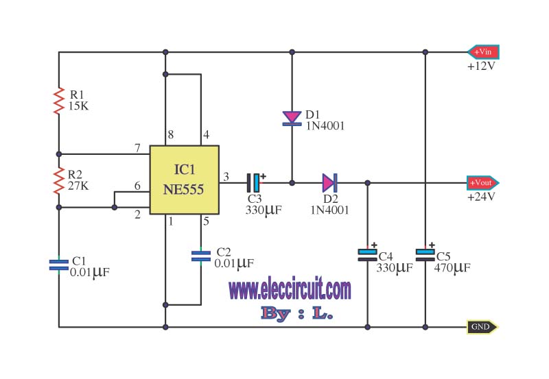
This is a simple voltage doubler circuit that converts 12V DC into 24V DC. It utilizes the popular NE555 timer IC along with a few additional components. The circuit can provide approximately 50mA of current, making it suitable for...
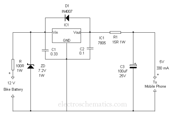
This is a simple and easy method to extract current from a motorcycle battery to charge a mobile phone. Most mobile phone battery packs consist of three 1.2 V cells. To effectively tap current from a motorcycle battery for mobile...
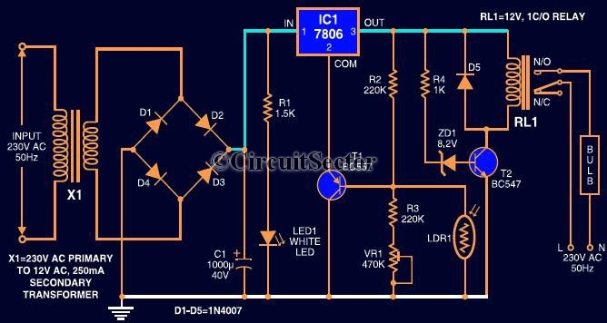
This circuit automates the control of street or porch lights. The automatic lamp controller circuit utilizes a 7806 voltage regulator IC, which can be employed to automate street lights, tube lights, or any other home electrical lighting systems. The...
The circuit was designed based on the functionality of a Class A amplifier to create a headphone circuit. A BC308 epitaxial planar PNP transistor is utilized. The Class A amplifier configuration is known for its linearity and low distortion, making...

When discussing fan control, there are generally two methods: linear control and pulse-width modulation (PWM) control. Linear control is the most commonly used method, which involves reducing the voltage supplied to the fan. For a fan rated at 12...