
Class A-Designed Headphone Amplifier Using BC308 Transistor

The Class A amplifier configuration is known for its linearity and low distortion, making it suitable for audio applications such as headphone amplification. In this specific circuit, the BC308 transistor serves as the primary amplifying element. This transistor is favored for its low noise characteristics and ability to handle small signal levels effectively.
The circuit typically includes a biasing network to set the operating point of the transistor in the active region, ensuring optimal performance. Resistors are used to establish the necessary biasing conditions, while capacitors may be integrated into the design to filter out unwanted high-frequency noise and provide stability.
Input coupling capacitors are employed to block any DC component from the audio source, allowing only the AC audio signal to pass through to the base of the transistor. The output stage is designed to drive headphones, which usually have a low impedance. Therefore, the circuit may include an output coupling capacitor to prevent any DC offset from reaching the headphones, ensuring that only the amplified audio signal is delivered.
Power supply decoupling capacitors are also essential in this design to maintain a stable voltage supply and minimize the effect of power supply fluctuations on the amplifier’s performance. Overall, this Class A headphone amplifier circuit, utilizing the BC308 transistor, is aimed at providing high-fidelity audio reproduction with minimal distortion and noise, making it suitable for high-quality headphone listening experiences.The circuit was constructed around the functionality of a Class A amplifier to create a headphone circuit. BC308 an epitaxial planar PNP transistor used.. 🔗 External reference
Related Circuits
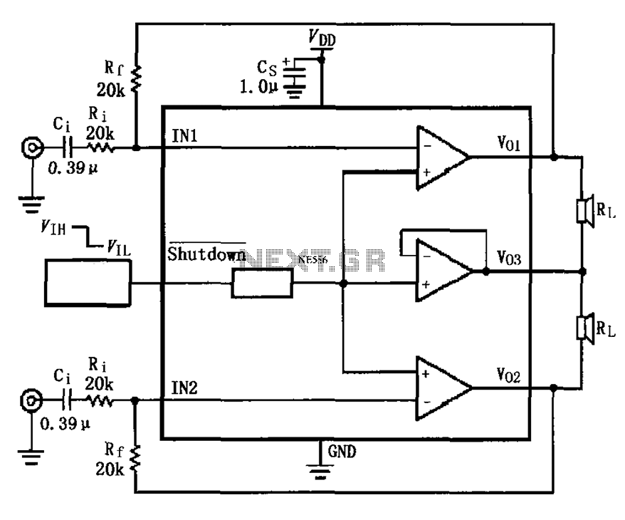
The LM4910 typical circuit is designed for a two-channel amplifier. The left and right channel audio signals are input to the LM4910 (in an MSOP/SO package) at pins 1 and 2. The output signals are delivered from pins 6,...
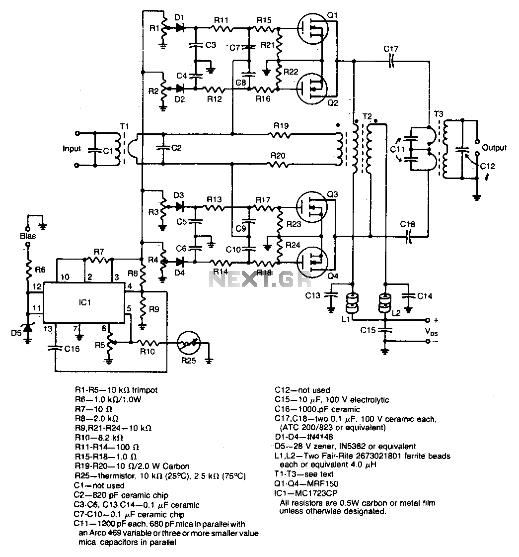
A unique push-pull parallel circuit utilizes four MRF150 RF power FETs connected in parallel at relatively high power levels. Supply voltages ranging from 40 to 50 Vdc can be employed, contingent on the linearity requirements. The bias for each...
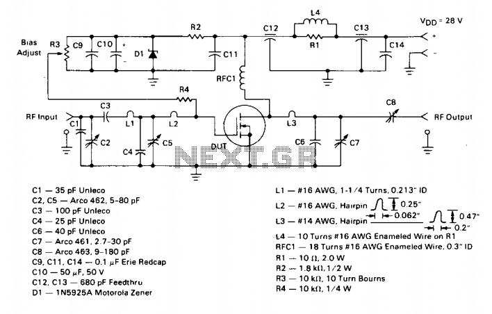
This amplifier operates from a 28 V DC supply. It has a typical gain of 12 dB and can withstand operation into a 30:1 VSWR load at any phase angle without sustaining damage. This indicates that with the input...
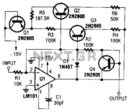
This operational amplifier circuit utilizes resistor and transistor feedback elements to function as a nonlinear amplifier. The resistors R4 and R6 can be adjusted to modify the breakpoints as needed. This operational amplifier circuit is designed to operate within the...
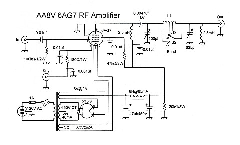
The input coupling capacitor allows the input signal to pass through to the grid of the tube while preventing the input source from potentially shorting the grid bias to ground. If the grid bias were shorted out, the 6AG7...
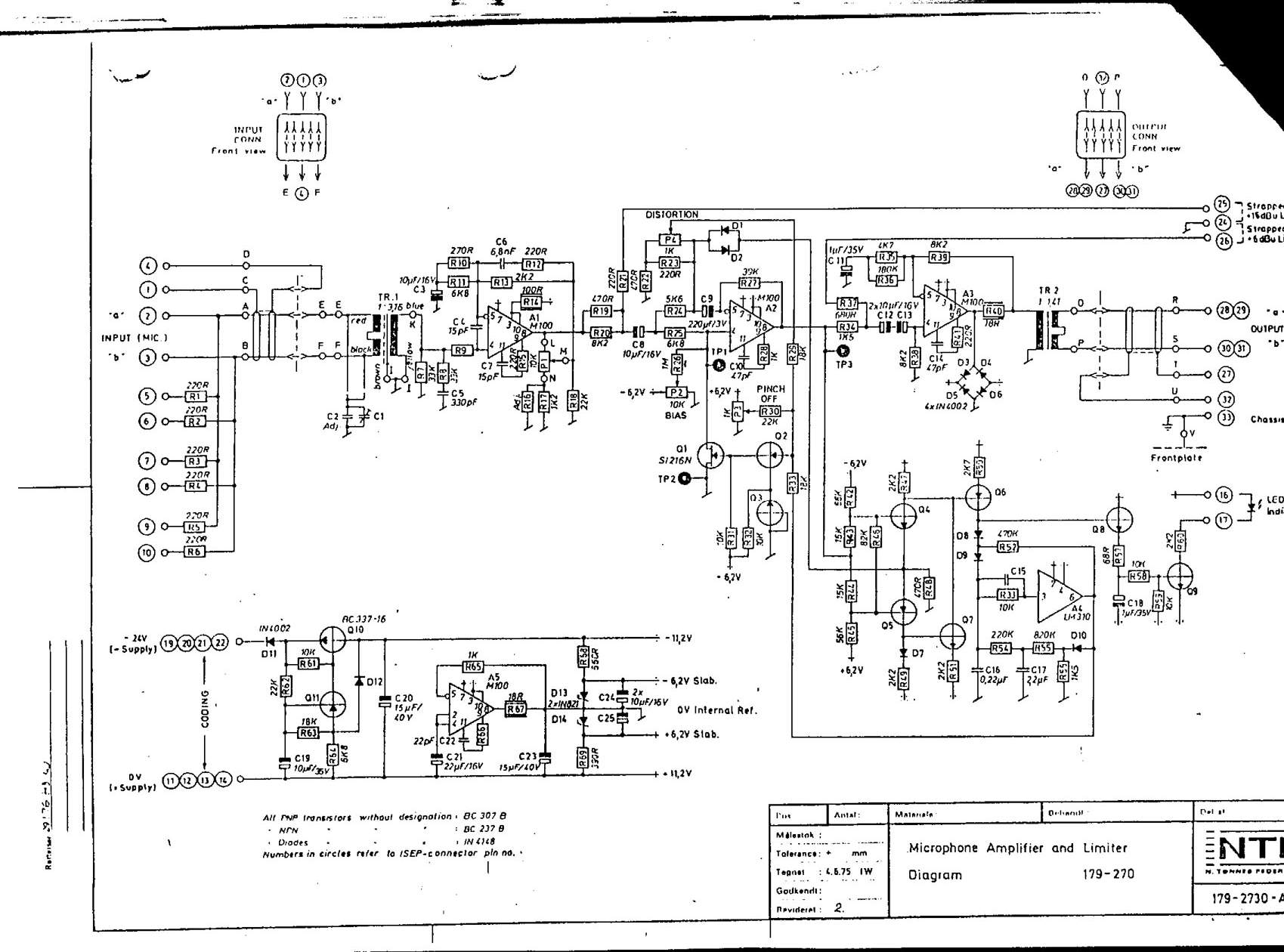
Here are some schematics and information that can be difficult to locate elsewhere. If there are schematics that should be included in this collection, please feel free to reach out. The intention is to expand this collection over time,...