
Led Flasher with a BC547 NPN transistor

The described flasher circuit utilizes a single driver transistor to control the flashing of a high-brightness white LED. The circuit operates by leveraging the charging and discharging characteristics of a 100µF electrolytic capacitor, which is crucial to the timing of the LED's illumination. The flash rate is inherently linked to the characteristics of the LED being used; specifically, a standard LED is unsuitable for this application, necessitating the use of a high-brightness variant.
In the configuration, a 1kΩ resistor is placed in parallel with the electrolytic capacitor to facilitate its discharge. This resistor plays a critical role in determining the brightness and flash rate of the LED. By adjusting this resistor to higher values, such as 4.7kΩ or 10kΩ, the discharge rate of the capacitor is altered, which in turn affects the flash intensity of the LED. When a higher resistance (like 10kΩ) is employed, the capacitor does not fully discharge, resulting in a dimmer flash from the LED due to insufficient current flow during the charging phase.
The transistor in the circuit acts as a switch, turning on when the capacitor begins to charge. The charging current flows through the LED, causing it to light up. The arrangement of components is critical; each part must be positioned according to the circuit diagram for optimal functionality. This circuit design is effective for applications requiring a simple flashing LED indicator, providing a clear visual signal while allowing for some degree of control over brightness through resistor selection.This is a novel flasher circuit using a single driver transistor that takes its flash-rate from a flashing LED. The flasher in the photo is 3mm. An ordinary LED will not work. The flash rate cannot be altered by the brightness of the high-bright white LED can be adjusted by altering the 1k resistor across the 100u electrolytic to 4k7 or 10k.
The 1k resistor discharges the 100u so that when the transistor turns on, the charging current into the 100u illuminates the white LED. If a 10k discharge resistor is used, the 100u is not fully discharged and the LED does not flash as bright. All the parts in the photo are in the same places as in the circuit diagram to make it easy to see how the parts are connected.
🔗 External reference
Related Circuits

This ultra-bright white LED lamp operates on 230V AC with low power consumption. It is suitable for illuminating VU meters, SWR meters, and similar applications. The cost of ultra-bright LEDs available in the market ranges from Rs 8 to...
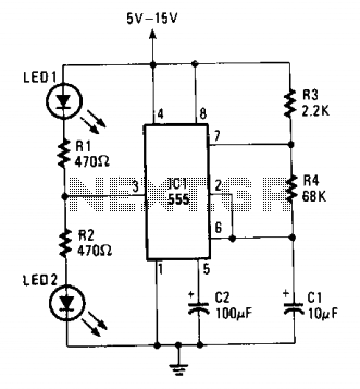
The flash rate is determined by CI and R4. The LEDs flash alternately. The circuit in question utilizes a timing mechanism where the flash rate of the LEDs is primarily governed by the capacitor CI and resistor R4. This configuration...

This single transistor audio mixer is utilized in an amplifier circuit design featuring a base-driven transistor, with its emitter being current-controlled. This audio mixer circuit employs a single transistor to facilitate the mixing of audio signals. The transistor operates in...

This is an integrated electronic mailbox circuit diagram designed for a front door. It activates when the door is opened. Additionally, when the cabinet photo detector is exposed to light, it will... The integrated electronic mailbox circuit is designed to...
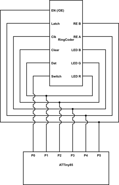
A chip conversion is being performed for the Sparkfun LED RingCoder. The sample code provided with the product functions effectively on an Arduino UNO, utilizing a separate pin for each input/output—specifically, five pins for the shift registers and six...
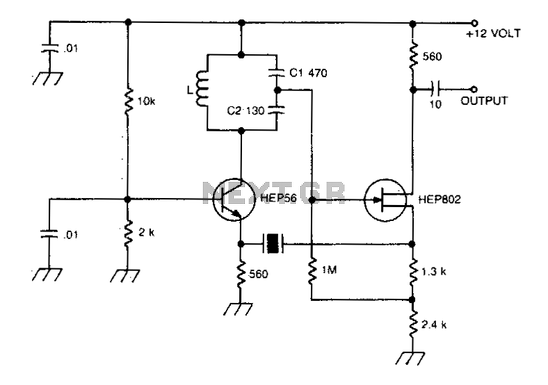
A typical Butler oscillator operating within the frequency range of 20 to 100 MHz incorporates a Field Effect Transistor (FET) in the second stage of its configuration. The circuit exhibits reliability issues when utilizing two bipolar transistors. In some...