
Electronic Mailbox Front Door With 2N3906 Transistor

The integrated electronic mailbox circuit is designed to enhance the functionality of a front door system. It typically includes several key components: a microcontroller, a photo detector, and various sensors to detect door status and light conditions.
The microcontroller serves as the central processing unit, receiving input from the door sensor and the photo detector. When the front door is opened, the door sensor triggers the microcontroller, which can activate a notification system, alerting the homeowner of the door's status. This could be in the form of a visual indicator, such as an LED, or an auditory signal, such as a chime.
The photo detector plays a crucial role in this circuit. It is designed to detect ambient light levels and can activate or deactivate certain functions based on these levels. For instance, if the cabinet photo detector detects sufficient light, it could signal the microcontroller to enter a low-power state or to deactivate the notification system during the day, thereby conserving energy. Conversely, in low-light conditions, the system could remain active to ensure that alerts are received when the door is opened.
The circuit may also include additional features such as a timer to manage how long the system remains active after the door has been opened, and a power management module to ensure efficient operation. Overall, this integrated electronic mailbox circuit provides a practical solution for monitoring door activity while minimizing unnecessary notifications and conserving energy.This is a integrated electronic mailbox circuit diagram, A front door open.And when people open. When the cabinet photo detector attached to the light, it will .. 🔗 External reference
Related Circuits
The main purpose of this design is to address a minor flaw in the widely used Fridge Door Alarm circuit, which has been available on this website since 1999 and has been constructed by many hobbyists. This circuit ceases...
This is a classic 2-transistor astable multivibrator. Many other NPN small signal or switching transistors can be used, including 2N4401, PN2222, or 2N2222 using the circuit on the left. The circuit can also be inverted using PNP transistors such...
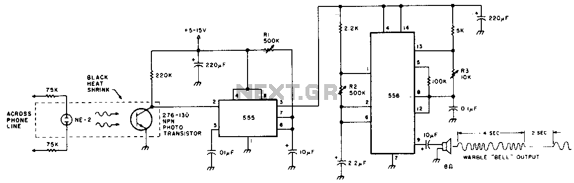
The speaker produces a unique warble tone when ring pulses are applied to the phone line. This circuit can be utilized as a remote bell or by disconnecting the phone's ringer for direct operation. Resistor R1 adjusts the output...

The circuit reduces voltage size or functions as a step-down voltage converter circuit, specifically a DC regulated circuit model using a switching converter. It generates the desired voltage output. The step-down voltage converter circuit, also known as a buck converter,...

This design was developed by request of a correspondent having made a sort of LED candle and needing to switch off the LED with a puff. This simple, easy to build gadget can be useful as a prop for...
The most challenging aspect of this circuit was determining its title. It can be easy to overlook the sound of a doorbell while watching television; this circuit addresses that issue by providing a visual indication, such as a lamp....