
LED Light Sequencer using 555

The circuit design employs a 555 timer IC configured in astable mode to generate a pulse-width modulation (PWM) signal. This signal is responsible for controlling the sequential lighting of multiple LEDs. The output from the 555 timer is connected to a series of transistors or MOSFETs that drive the LEDs, ensuring that they can handle the required current without damaging the 555 IC.
In this setup, resistors and capacitors are used to set the timing characteristics of the 555 timer, determining the frequency and duration of the LED flashes. The circuit can be designed to light up the LEDs in a left-to-right or right-to-left sequence, depending on the desired application. Additional components, such as diodes, may be included to protect against reverse polarity and to ensure that the current flows in the intended direction.
The power supply for the circuit can be derived from the vehicle's battery, typically 12V for automobiles or 6V for bicycles, with appropriate voltage regulation if necessary. The design should also consider the use of a microcontroller for more complex sequencing patterns, should the application require it.
This LED indicator project not only enhances safety by providing clear signaling during turns but also adds an aesthetic appeal to the vehicle or bicycle. Proper placement of the LEDs is crucial for visibility and effectiveness in signaling to other road users.Another 555 IC project that will flash LEDs in such a way that light turns on in a sequence. You can use this as an indicator for turning left or right for vehicles and bikes. 🔗 External reference
Related Circuits
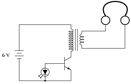
If you do not have an audio detector already constructed, a set of closed-cup audio headphones that completely cover the ears, along with a 120V/6V step-down transformer, can be utilized to create a sensitive audio detector for this experiment....
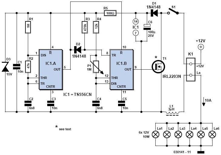
A light dimmer is quite uncommon in a caravan or on a boat. This document outlines how to create one, allowing for mood adjustment when needed. A light dimmer circuit is an essential component for enhancing the ambiance in confined...
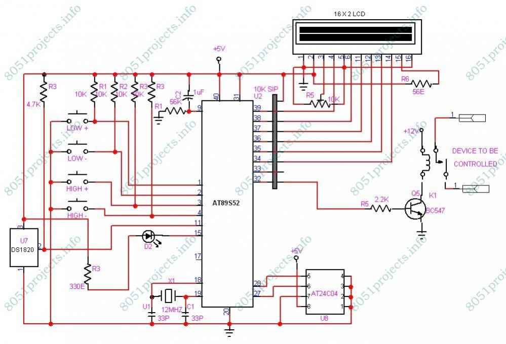
This project is designed to monitor and control temperature. The system utilizes the DS1820 temperature sensor to measure the temperature, which is then displayed on an LCD. It features two preset levels: a low preset and a high preset....
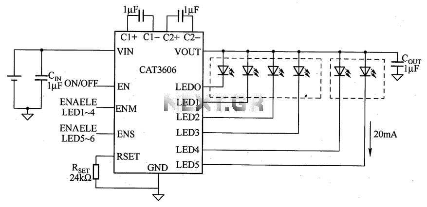
CAT3606 is a high-efficiency white LED driver. This adjustable charge pump is suitable for general-purpose, large-panel, flicker-free white LED backlighting and dual-display systems. The CAT3606 inductor boost circuit can replace conventional high-brightness backlighting requirements, thereby simplifying system design. It...
There are many who built the Easy Programmer or C-52 Evaluation Board, asking for the RS232C level converter chip, DS275. Many have changed to MAX232 instead, because it is not available in their home. Here is another simple and...
This is a programmable clock timer circuit that uses individual LEDs to indicate hours and minutes. 12 LEDs can be arranged in a circle to represent the 12 hours of a clock face and an additional 12 LEDs can...