
Led Millivoltmeter

The circuit employs the LM324 operational amplifier, which is a versatile device commonly used in various analog applications. It features four independent, high-gain, frequency-compensated operational amplifiers, allowing for efficient amplification of small voltage levels. In this configuration, the LM324 is set to a gain of 100, which is achieved through a feedback resistor network that determines the gain of the amplifier. This configuration allows the circuit to detect voltage levels as low as 1 mV, enhancing the sensitivity significantly.
The LM339 quad comparator is integrated into the circuit to compare the amplified output of the LM324 against predetermined reference voltages. Each comparator within the LM339 can be configured to trigger an LED when the input voltage exceeds specified thresholds. In this case, the design allows for the illumination of LEDs for every increment of 100 mV, creating a visual representation of the voltage levels.
The auxiliary LEDs serve important functions as well. The "power on" LED provides a clear indication that the circuit is powered and operational, ensuring user awareness of the system status. The second auxiliary LED, labeled "x100," signifies that the gain setting is active, providing an additional layer of information regarding the circuit's operational mode.
Overall, this circuit design effectively combines amplification and level sensing to create a straightforward bar-graph display, making it suitable for applications requiring visual voltage monitoring. The careful selection of components and their configurations ensures reliable performance and clear user feedback. This circuit uses a dc amplifier (324) in a bar-graph circuit that uses an LM339 Quad comparator IC to sense dc levels. The LEDs will light every 100 mV. The 324 op amp is configured to provide a gain of 100 to increase this sensitivity to 1 mV. Two auxiliary LEDs indicate "power on" and "xlOO" gain setting.
Related Circuits

A radio-controlled electronic flash is an essential tool for any photographer's kit, frequently utilized by professionals. For instance, a wedding photographer may position one behind the bride to illuminate her gown and veil without visible wires in the shot....

The Spartan-6 board features 16 LEDs connected to FPGA I/O pins, as detailed in the table below. The cathode of each LED is connected to ground through a 330-ohm resistor. To illuminate a specific LED, the corresponding FPGA control...

The 5AH will trigger when the voltage across the two 0 µF capacitors reaches the breakdown voltage of the lamp. Control can be obtained from full off to 95% of the half-wave RMS output voltage. Full power can be...

There are many applications where the accuracy of a digital or analog (bar graph) output is not necessary, but a solution that offers more than a simple low/high indicator is desirable. In various electronic applications, there exists a need for...
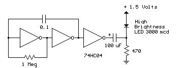
Several 1.5 V LED flasher circuits can be found online, and four of them are presented here. The flasher circuits operate on a single 1.5 V power supply. The design of a 1.5 V LED flasher circuit typically involves a...

The 8051 controller is mask-programmable, meaning it is programmed during manufacturing and cannot be reprogrammed afterward. However, the AT89C51 microcontroller, a derivative of the 8051, is reprogrammable. This device includes a timer, a serial port interface, and interrupt control,...