
LED Power Meter

The LED power meter circuit operates as a straightforward RF power detection system. It employs a pair of diodes configured as a rectifier to convert the RF signal into a DC voltage, which is then stored in a capacitor. The capacitor's voltage is indicative of the RF power level present at the input, which can be measured using a multimeter.
The circuit can be assembled without a printed circuit board (PCB), facilitating rapid prototyping and testing. The use of paper clips as terminals allows for easy connection to the multimeter, ensuring that the circuit can be adjusted or modified with minimal effort. The LED serves as a visual indicator of RF presence; when the output from an FM transmitter is sufficiently strong, the LED will illuminate, providing immediate feedback on the operational status of the RF signal.
While the circuit is designed for simplicity, it is important to note that the accuracy of the voltage readings can be affected by the type of multimeter used. Digital multimeters may display erroneous readings due to the high-frequency nature of the RF signals, while some analogue meters may experience full-scale deflection, making it difficult to obtain precise measurements. This phenomenon occurs because the RF energy can induce significant voltages that exceed the expected range of the meter.
Overall, this LED power meter circuit serves as an effective tool for detecting RF signals and provides a practical approach for hobbyists and engineers to measure RF power levels with minimal complexity.The LED power Meter is a simple RF detector using diodes to charge a capacitor. The voltage developed across the capacitor is indicated by a multimeter set to a low voltage range. The circuit is soldered together without the need for a PC board, as can be seen in the diagram below and paper clips are used for the positive and negative terminals of the multimeter. It will only take a few minutes to put this circuit together. The power from the output of an FM transmitter is indicated by the illumination of a LED and the voltage reading on the multimeter gives a further indication of the output.
A digital multimeter may be used but the presence of RF may produce a false reading. Likewise, the radiated energy may upset some analogue meters and you may get full scale deflection on the 15v range as well as the 250v range! But the LED won`t li 🔗 External reference
Related Circuits
This circuit will flash a super-bright LED (5000+ mcd). Good for fake car alarm or other attention-getting device. Component values are not critical; try anything else first from your junk box. Obviously, the 470 ohm resistor (R3) determines the...
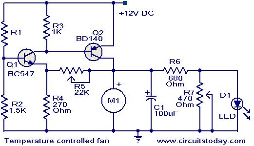
This circuit utilizes two transistors to regulate the speed of a 12 V DC fan based on temperature changes. A thermistor (R1) detects the temperature. As the temperature rises, the base current of transistor Q1 (BC 547) increases, leading...

The motor vehicle currently represents a no-emission automotive solution, serving as a green means of transportation that is expected to significantly impact human society in the 21st century. The direct-flow brushless electric machine has emerged as a leading technology...

This circuit performs a rapid battery test without requiring a power supply or costly moving-coil voltmeters. It features two ranges: when SW1 is configured as depicted in the circuit diagram, the device can test batteries ranging from 3V to...
The circuit is connected in parallel with the output of a power amplifier and provides the signal level from the output. By adjusting the resistance R1 in the input circuit, the power indication can be adapted to the resistance...

The SSY-1 is a compact pulsed Nd:YAG laser that was initially utilized as part of the laser rangefinder in the M1 Abrams tank. The laser head and PFN-1 pulse forming network, which includes a flashlamp capacitor, inductor, and diode,...