
led sequencer chaser ne555 4017

The LED sequencer circuit operates by leveraging the capabilities of both the CD4017 and NE555 ICs to produce a dynamic light display. The NE555 timer is configured in an astable mode, which means it continuously oscillates between its high and low states. This oscillation generates a square wave output that serves as the clock signal for the CD4017 counter.
The CD4017 counter has ten output pins (Q0 to Q9), each corresponding to a specific count of the clock pulses it receives. As the NE555 generates clock pulses, the CD4017 advances its count with each pulse, sequentially activating each output pin in turn. This results in a chaser effect as the LEDs connected to these output pins light up one after the other in a cascading manner.
The design of this circuit is straightforward. The NE555 timer requires a resistor-capacitor (RC) network to set the frequency of the oscillation, which determines the speed of the LED chase effect. By adjusting the values of the resistors and capacitors in the NE555 circuit, the timing can be modified, allowing for control over the rate at which the LEDs light up.
In practical applications, this LED sequencer can be used for decorative lighting, indicators, or in displays where a visually striking light pattern is desired. The simplicity of the circuit also makes it suitable for educational purposes, allowing learners to understand the operation of counters and timers in electronic circuits. Proper power supply and grounding should be ensured to maintain the functionality of both ICs, and appropriate current-limiting resistors may be used for the LEDs to prevent damage.Here is a circuit of a LED sequencer / chaser using CD 4017 and NE555 IC. CD 4017 is a CMOS counter IC consist of 16 pins. This IC gives 10 outputs according to the clock pulse it receives from the clock input, which is pin 14. The another IC used in this circuit is NE555 which is a timer IC. NE555 is a very famous IC and used in wide verity elect ronic projects to perform different tasks. In this circuit it is working as an astable multivibrator and its providing continuous clock pulses to the CD 4017 IC. Due to which CD 4017 produces very beautiful looking chasing light effects. 🔗 External reference
Related Circuits
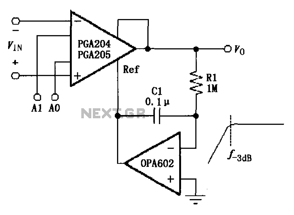
The circuit depicted in the figure features a programmable amplifier utilizing the PGA204/205 operational amplifiers in conjunction with the OPA602. The OPA602 op-amp is configured to establish a feedback reference point, while external components, specifically the capacitor C1 and...

This circuit is designed as a warning flasher to alert road users to dangerous situations in low-light conditions. It can also function as a bicycle light, subject to applicable traffic regulations. White LEDs are recommended for use as a...
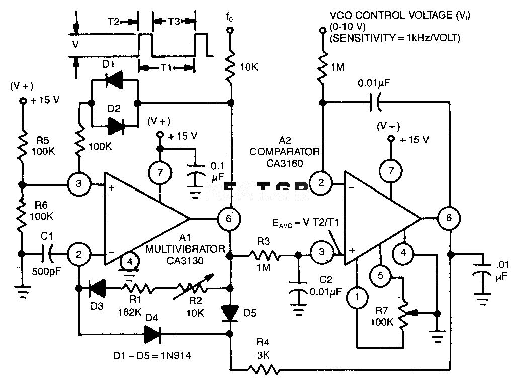
This circuit utilizes a CA3130 BiMOS operational amplifier as a multivibrator and a CA3160 BiMOS operational amplifier as a comparator. The oscillator exhibits a sensitivity of 1 kHz/V, with a tracking error of approximately 0.02% and a temperature coefficient...

The circuit illustrated in Figure 1 generates a precise variable-frequency sine wave intended for use as a general-purpose reference signal. It incorporates an 8th-order elliptic switched-capacitor low-pass filter (IC3), which is clocked by a 100 kHz square wave produced...
This circuit uses two quad op-amps to form an eight LED audio level meter. The op-amp used in this particular circuit is the LM324. It is a popular IC and should be available from many parts stores. More: The...
This circuit uses three easily available 555 timer ICs. All three work as astable multivibrators. The first 555 has an on period and off period equal to 1 sec. This IC controls the on/ off periods of the other...