
LED Solar Lantern Lights Circuit

The schematic for the LED solar lantern circuit incorporates a solar panel that converts sunlight into electrical energy. The 6V/1W solar panel is connected to a charge controller which regulates the voltage and current flowing into the 4V/800mAh lead-acid battery. This battery serves as the energy storage component, allowing the lantern to operate during periods of low or no sunlight.
The circuit includes a blocking diode connected in series with the solar panel to prevent reverse current flow from the battery to the panel during nighttime or low-light conditions. This diode ensures that the battery maintains its charge and does not discharge back into the solar panel, which could lead to battery depletion.
The LED lights are connected to the output of the battery, typically through a switch that allows the user to turn the lantern on and off as needed. The LEDs are chosen for their low power consumption and high efficiency, maximizing the battery life and ensuring adequate illumination.
To enhance performance, a voltage regulator may be included to ensure that the voltage supplied to the LEDs remains stable, regardless of variations in the battery voltage as it discharges. This is particularly important for maintaining consistent brightness levels and prolonging the lifespan of the LEDs.
Overall, this solar lantern circuit is a sustainable solution for outdoor lighting, utilizing renewable energy to power efficient LED lights, making it an eco-friendly choice for various applications.Circuit of the LED solar lantern lights presented here is built around one 6V/1W Solar Panel (PhotoVoltaic Panel) and a 4V/800mAh Lead-Acid Battery. Here,.. 🔗 External reference
Related Circuits
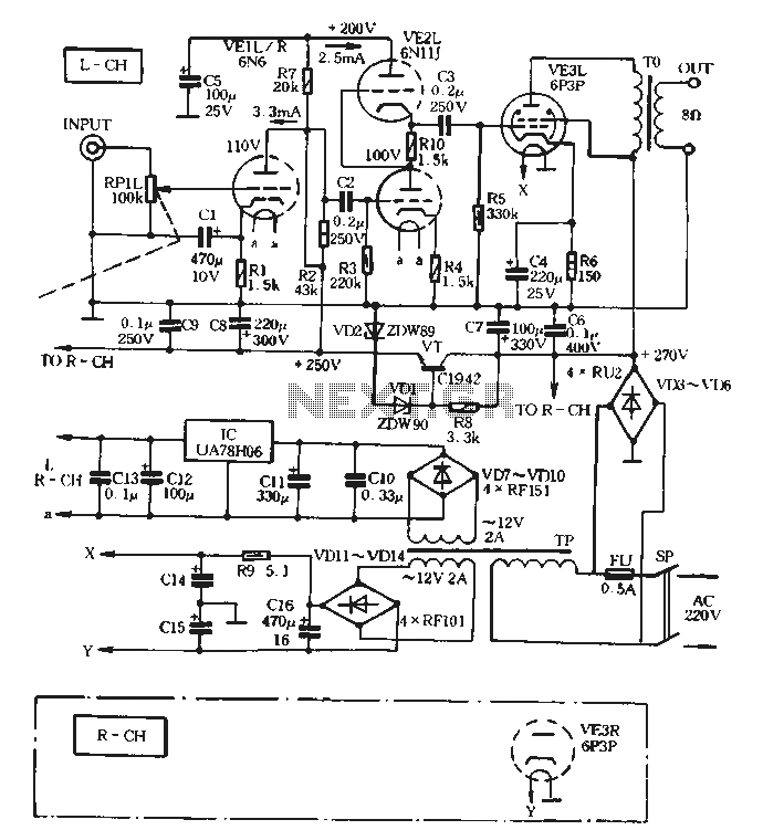
The VE1 preamplifier utilizes a low muscle, low resistance double triode 6N6 configuration, with separate halves for the left and right audio channels. The design operates within the CPI framework. It promotes the use of high-level VE2 household low...
A collection of guitar fuzz, preamp, and operational amplifier (op-amp) electronic circuits and schematics designed for various guitar effects and distortion effects. This compilation includes a diverse range of electronic circuits that cater to guitarists seeking to enhance their sound...
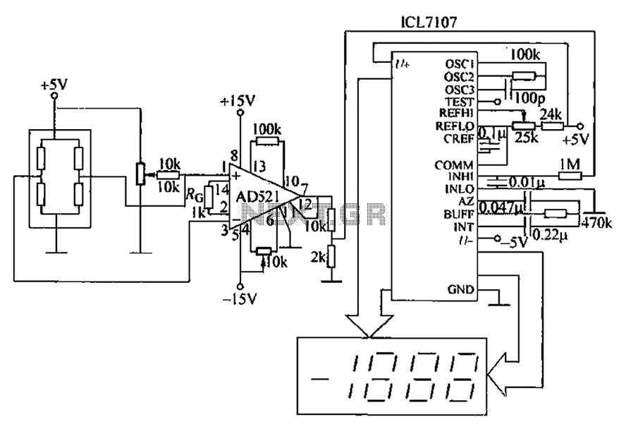
A pressure sensor circuit features a pressure sensor with a nominal resistance of 120 ohms. The amplifier circuit utilizes an AD521 operational amplifier with a gain of 100. It includes resistor components Rs and Rc, along with a decision-making...
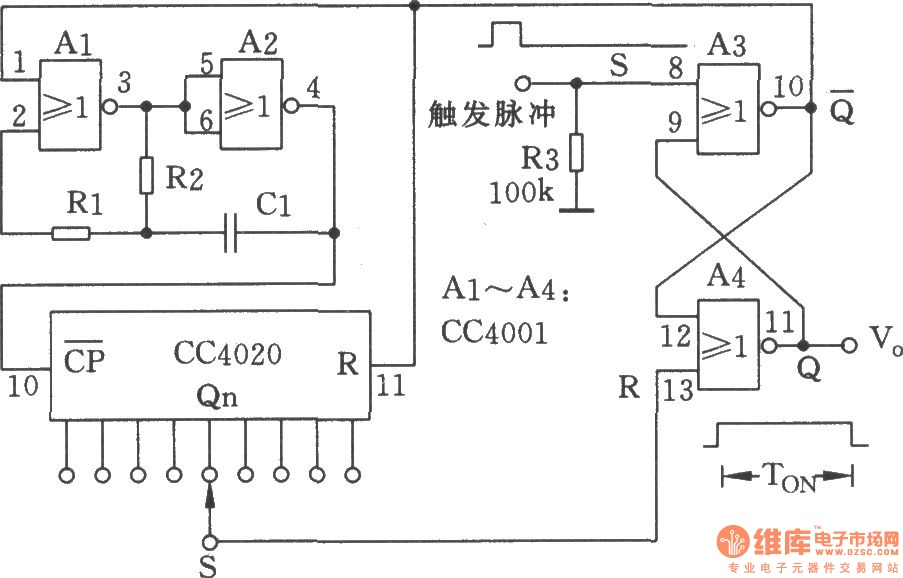
The NC monostable multivibrator circuit depicted in the chart consists of four 2-input NOR gates (CC4001) and a 14-bit binary serial counter/divider (CC4020). It is primarily utilized as a time delay switch or timer in automatic control equipment. The NC...
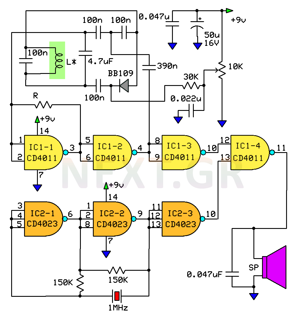
This circuit is a metal detector designed to detect large metallic objects at depths ranging from 2 to 3 meters, depending on the size of the object and the type of soil. The construction is straightforward, making it accessible...

This straightforward design of an inverter circuit is capable of delivering high output power with an efficiency of approximately 75%. It provides guidance on constructing an inverter that can meet most power requirements at a reasonable cost. The article...