
Guitar Circuits Amps and Effects

This compilation includes a diverse range of electronic circuits that cater to guitarists seeking to enhance their sound with fuzz, distortion, and preamplification effects. Each circuit is designed to modify the audio signal in unique ways, allowing for a wide array of tonal possibilities.
1. **Guitar Fuzz Circuits**: Fuzz circuits are known for their ability to create a rich, saturated sound that adds warmth and character to guitar tones. Common designs include the classic Fuzz Face, which utilizes transistors to achieve its signature sound, and the Big Muff, known for its sustain and harmonically rich distortion. These circuits typically consist of a gain stage, followed by clipping diodes that produce the desired fuzz effect.
2. **Preamp Circuits**: Preamp circuits serve to boost the guitar signal to line level, making them essential for driving amplifiers or effects pedals. They can be designed using op-amps or discrete transistor configurations. A common approach is to use an op-amp in a non-inverting configuration, providing high input impedance and low output impedance, which preserves the tone of the guitar while amplifying the signal.
3. **Operational Amplifier (Op-Amp) Circuits**: Op-amps are versatile components that can be used in various configurations to achieve different effects. They can be employed in filters, mixers, and gain stages. For example, an op-amp can be configured as a low-pass filter to remove high-frequency noise, or as a summing amplifier to combine multiple signals. Utilizing feedback and gain control, op-amps can shape the audio signal in numerous ways, making them invaluable in the design of guitar effects.
4. **Distortion Effects**: Distortion circuits generally combine elements of fuzz and overdrive to create a more aggressive sound. They often incorporate both clipping diodes and gain stages to achieve a range of distortion characteristics, from subtle warmth to heavy saturation. Popular designs include the Tube Screamer, which utilizes op-amps to emulate the warmth of a tube amplifier.
These circuits can be implemented on printed circuit boards (PCBs) or breadboards for prototyping. Each schematic typically includes component values, pin configurations, and layout guidelines to assist in the construction process. Comprehensive knowledge of electronic components, soldering techniques, and circuit analysis is essential for successful implementation and troubleshooting of these guitar effects circuits.List of Guitar Fuzz, PreAmp, OpAmp electronic circuits and electronic schematics for a variety of Guitar effects and distortion fx.. 🔗 External reference
Related Circuits
The PhoneAxe is a unique design that incorporates a passive filter network within a 1/4" phone plug/coaxial cable. It is specifically engineered to facilitate the matching of electric guitars to the magnetic phono input found on standard hi-fi amplifiers....
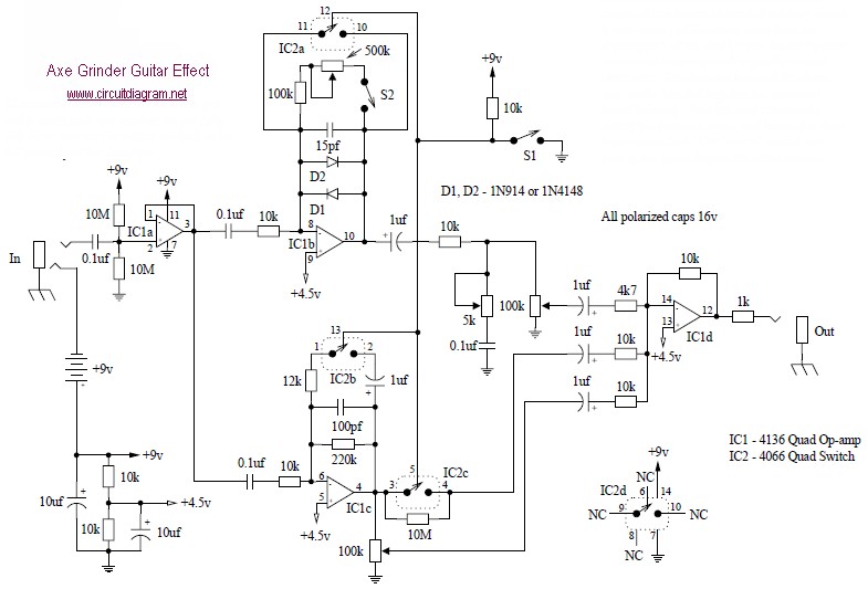
The Axe Grinder is designed with several key features in mind. It serves a wide range of distortion sounds by clipping part of the effect and allows users to overload their amplifier with a significantly boosted clean tone. The...
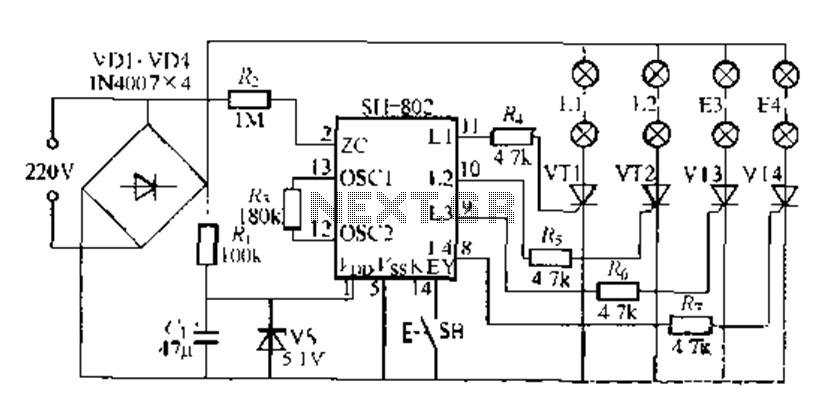
A digital integrated circuit simplifies the response process significantly. The diagram illustrates a circuit comprising four responder groups. The digital integrated circuit described serves as a crucial component in various electronic systems, primarily focusing on enhancing response efficiency. It comprises...
This guitar effect circuit employs a straightforward high-gain amplification stage, succeeded by symmetric clipping achieved through a parallel diode clipper. The gain is provided by a 741 operational amplifier. The circuit design begins with a high-gain amplification stage utilizing the...
This is another kit in our self-sufficiency range. We also have a 12v fluoro inverter kit for those who need to operate 20watt to 40watt fluorescent lamps from a 12v supply. We will be introducing a number of kits...
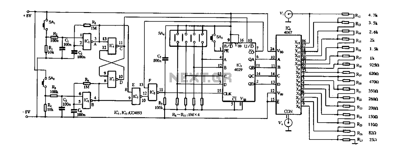
Figure 4-14 illustrates a digital integrated circuit featuring 16 preset potentiometers for Siniperca electronic circuits. The circuit comprises three main components: an input controller, a presettable counter, an analog electronic switch, and a resistor network. It includes a push-button...