
LED Sound level display circuit by using IC LM3915

The audio sound level LED display circuit utilizes the LM3915 integrated circuit, which is designed for visualizing analog signals through a series of LEDs. This circuit is particularly useful for audio applications, where it provides a clear visual representation of sound levels. The LM3915 features a built-in logarithmic scale, allowing it to respond to sound levels in a manner that is perceptually relevant to human hearing, where sound intensity is typically perceived on a logarithmic scale.
The circuit is powered by a DC supply, with a recommended range of 9V to 12V for optimal performance. This voltage range ensures that the LEDs operate efficiently, providing adequate brightness while minimizing power consumption. The inclusion of a 10K ohm potentiometer allows for manual adjustment of the LED brightness, which can be particularly useful in different ambient light conditions or for different user preferences.
The audio input is connected to Pin-5 of the LM3915, which accepts a varying voltage signal corresponding to the audio level. This signal can be taken from various audio sources, including the output of an audio amplifier or other audio devices. The circuit's design supports versatility in application, making it suitable for home audio systems, musical instruments, or sound level monitoring in various environments.
Pin-9 serves a crucial function in the display mode selection, allowing users to choose between a dot mode, where a single LED indicates the current sound level, and a bar mode, where multiple LEDs light up to create a visual representation of the sound level. The ability to switch between these modes enhances the circuit's flexibility, catering to different display preferences or requirements for specific applications. Disconnecting Pin-9 from the positive voltage supply enables the dot mode, providing a dynamic visual cue that can be particularly engaging in live sound settings or performances.
Overall, this audio sound level LED display circuit is a straightforward yet effective solution for visualizing audio levels, leveraging the capabilities of the LM3915 integrated circuit to deliver a user-friendly and adaptable display system.This is a simple audio sound level LED display circuit diagram. The circuit is completely based on a single ic LM3915 from National Semiconductor. The LM3915 is a monolithic integrated circuit. It displays the audio sound level in terms of 10 LEDs and providing a logarithmic 3 dB/step analog display. The audio sound level LED display circuit can o perate from a single supply 3V to 25V. But I suggest to use 9-12V. LED brightness can be controlled with a single pot( variable resistor) as shown 10K ohm in the circuit. Connect the audio input signal in Pin-5 of LM3915 from output of a audio device like output of audio amplifier or any other source.
The Pin-9 of LM3915 is to select dot or bar mode display. To make the circuit moving dot display instead of a bar graph display disconnect the Pin-9 from +V. 🔗 External reference
Related Circuits

Channel 7 presents a circuit diagram of a smart temperature sensor using the MAX6698. This circuit includes three transistors (VT1, VT2, and VT3) and three thermistors (RT1, RT2, and RT3). An internal reference voltage source is provided via resistors...
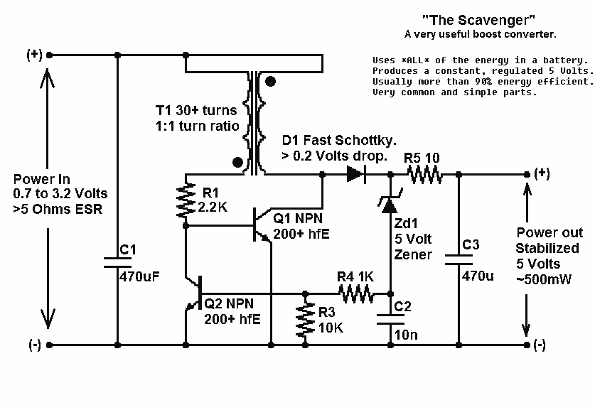
Presented here is a significant advancement in the design of simple, cost-effective, and efficient boost converters. To achieve an effective design, it is essential to convert current to voltage as efficiently as possible. This circuit excels in this regard. The...
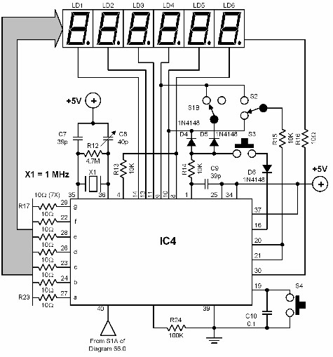
A digital audio frequency (AF) counter can be constructed using a minimal number of components by employing a single 7226B integrated circuit (IC) from Intensil, as depicted in the accompanying diagram. This circuit has an upper frequency limit of...
When power is applied, the 15K resistor and 10µF capacitor at pin 15 will reset the counters to a zero count, with pin 3 at +12V and all other outputs at zero. The two diodes (1N914) and a 15Ω...
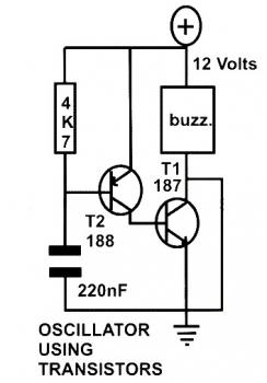
This schematic diagram represents a basic oscillator circuit utilizing two transistors. When the transistors and several passive components are connected as illustrated, the circuit begins to oscillate. The oscillation frequency can be modified by altering the values of either...
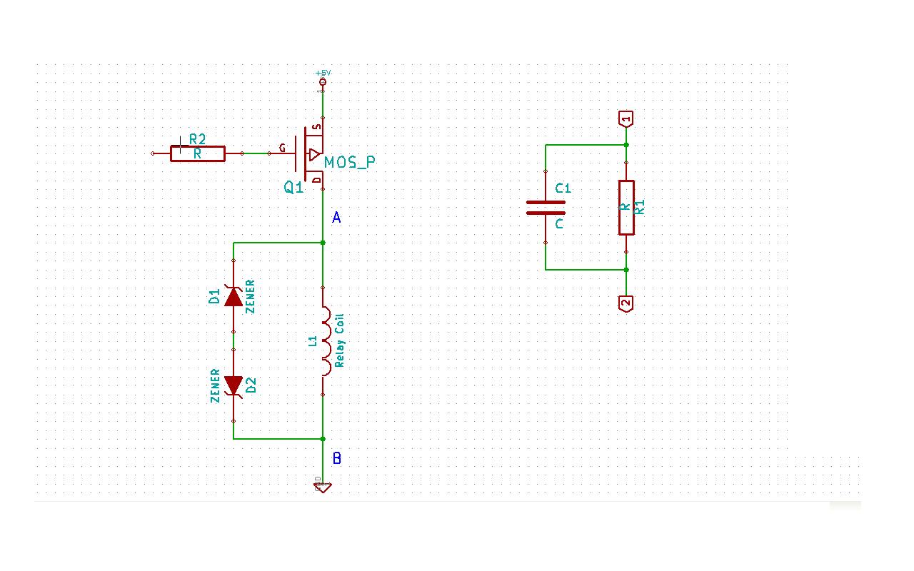
Although this may be a basic question, there is still some struggle with it. In this schematic, two zener diodes D1 and D2 are connected back-to-back across relay coil L1. The breakdown voltage (BVds) is -30V for Q1. The...