
Common collector amplifier circuit DC and AC path b

The common collector amplifier, also known as an emitter follower, is a configuration that provides voltage gain while maintaining a low output impedance. It is particularly useful for impedance matching between different stages of a circuit. The circuit comprises a bipolar junction transistor (BJT) with its collector connected to the power supply and the emitter connected to the load. The input signal is applied to the base of the transistor.
In the DC analysis, the biasing network is crucial for the proper operation of the amplifier. Typically, resistors are used to set the base voltage, ensuring that the transistor operates in the active region. The DC path allows for the establishment of a stable operating point, which is essential for linear amplification. The bias current flowing through the transistor is determined by the values of the resistors in the biasing network and the power supply voltage.
For AC analysis, the circuit's behavior is examined under small-signal conditions. The coupling capacitor, connected at the input, blocks any DC component of the signal while allowing AC signals to pass. This capacitor effectively shorts the AC signal to ground at higher frequencies, ensuring that the transistor responds only to the variations in the input signal. The output voltage follows the input voltage, minus the base-emitter voltage drop, which is typically around 0.7V for silicon transistors.
In summary, the common collector amplifier is an essential building block in analog electronics, providing efficient signal buffering and impedance transformation. Its design considerations, including biasing and coupling, are critical for achieving the desired performance in various applications. Common collector amplifier circuit DC and AC path b (3) common-collector amplifier circuit DC and AC path when common collector amplifier circuit for analysis, can be divided i nto DC and AC two paths, as shown in FIG. The DC path to provide a DC bias circuit of the circuit from the power transistor, the transistor is in an enlarged state or the off state, it is mainly determined by the bias. This circuit also provides energy for the transistor circuit. AC AC signal path is functioning circuit, a capacitor AC signal can be regarded as a short circuit, the internal resistance of the power supply also depends on the AC signal is short-circuited.
Related Circuits
The 30-watt amplifier schematic provided below offers a power boost from an input of 4 watts to 6 watts. This circuit is designed to operate within the 88-108 MHz FM broadcast band. It demonstrates stability and delivers a clean...
This circuit turns off an amplifier or any other device when a low-level audio signal fed to its input is absent for at least 15 minutes. Pressing P1 switches the device on, supplying power to any appliance connected to...

To get a low output impedance I needed to use quite a high step-down ratio (20:1); after all, the amplifier may be used with headphones of lower impedance than the 300 Ohms of the HD600. The output valve is...
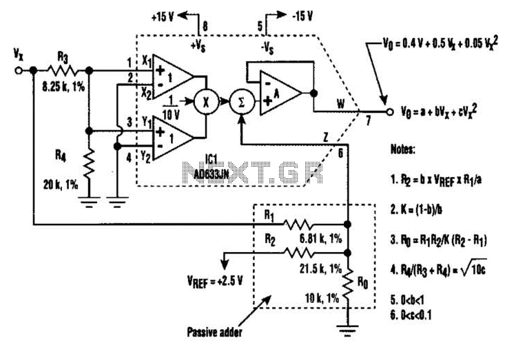
A circuit utilizing a single analog multiplier and five precision resistors can produce an output voltage (Ko) that represents a second-order polynomial. This circuit implements the quadratic function. The input terminals of IC1 are configured to create a positive...

The CXA1600M and CXA1600P are 8-pin single-chip bipolar integrated circuits (ICs) designed for AM radios. These ICs encompass all necessary functions from the front-end to the power amplifier, eliminating the need for external filters, which makes the attachment of...
This discussion covers three different Xenon flashing circuits from disposable cameras. From these circuits, unique techniques not found in any theoretical literature will be presented. The first circuit consists of six building blocks. An old disposable flash camera and...