
LED stepdown power supply
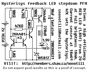
The described circuit functions as a proof of concept for a step-down (buck) converter designed primarily to drive a red LED with a forward voltage (Vf) of 1.9V using two nickel-cadmium (NiCd) batteries, allowing operation down to a voltage level of 2 volts. The circuit's design is notable for its efficiency, particularly in low-voltage applications, where the current sensing mechanism detects a minimal voltage drop of 18mV across a 1-ohm resistor. This low sensing voltage suggests that the circuit can monitor and regulate current effectively while maintaining high efficiency.
For applications requiring a white LED, which typically has a higher forward voltage than red LEDs, additional battery cells are necessary to meet the voltage requirements. Furthermore, the 1.0K ohm resistor, which is part of the feedback and control loop, must be increased to accommodate the higher current demands of the white LED.
The circuit employs a current mirror configuration, which is critical for maintaining stable operation and ensuring that the output current remains consistent despite variations in input voltage or load conditions. The inclusion of a 47K hysteresis resistor provides positive feedback from the driver transistor back into the current mirror, enhancing the circuit's stability and performance as a switching power supply. This feedback mechanism allows the circuit to switch efficiently between on and off states, thereby minimizing power loss.
To further enhance the efficiency of the step-down converter, several modifications can be considered. Utilizing a larger inductor can improve energy storage and transfer during the switching cycles, reducing ripple current and improving overall performance. Additionally, optimizing the switching speed of the transistor can minimize transition losses, contributing to better efficiency. Lastly, increasing the value of the 1.0K resistor can help manage output current more effectively, especially when driving higher-power LEDs.
It is important to note that the circuit can also be configured to operate in linear mode if the hysteresis resistor and inductor are removed. In this mode, the circuit would function differently, potentially providing a simpler linear regulation, but at the cost of efficiency, particularly in applications where the input voltage significantly exceeds the output voltage.Below is a proof of concept circuit which needs improvement. The part values shown will run a high efficiency red LED with a Vf of 1.9V from only 2 nicads, right down to 2 volts. For a white LED you will need more batteries and you must increase the 1.0K resistor to a higher value.
Current sensing at a mere 18mV over 1ohm makes this stepdown switcher efficient, but efficiency can be increased by using a larger inductor, improving transistor switching speed, or by increasing the value of the 1.0K resistor. Positive feedback from the driver transistor back into the current mirror through the 47K hysterisys resistor ensures that this circuit behaves as a switching power supply, however it could be used in linear mode if this resistor and the inductor were removed.
🔗 External reference
Related Circuits
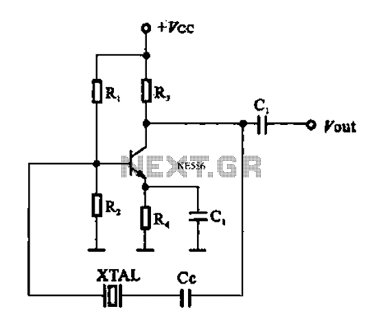
A series resonant circuit utilizing a crystal oscillator is illustrated. The crystal impedance reaches a minimum value at the series resonance frequency, resulting in a significant feedback amount. The crystal tuning capacitor (Cc) can slightly adjust the resonance frequency...
This article was previously published, but the intention is to spread the idea further, potentially inspiring new concepts. An improved version was being developed using an ULN2803A instead of multiple BC547B transistors and optional Zener diodes to ensure that...
This compact switching power supply utilizes a Schmitt trigger oscillator to control a switching transistor, which provides current to a small inductor. When the transistor is activated, energy accumulates in the inductor, and this energy is subsequently released into...
This project flashes eight LEDs in an apparently random manner. It uses a 4060 combined counter and display driver IC which is designed for driving 7-segment LED displays. The sequence is not really random because seven of the LEDs...
Savings on electricity bills can be achieved by utilizing alternative power sources. The photovoltaic module, or solar panel, described here can provide a power output of 5 watts. Under full sunlight conditions, the solar panel generates an output voltage...
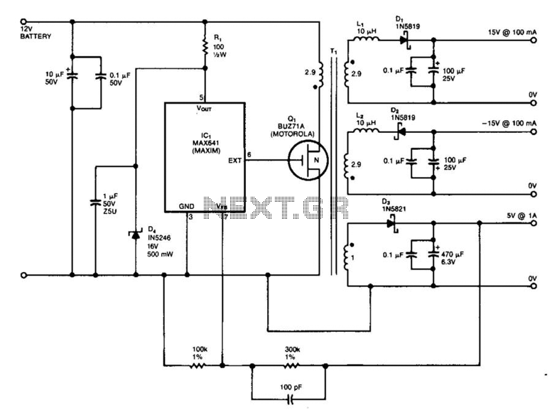
IC1 is a switching regulator that generates a 45-kHz signal to drive the gate of MOSFET Q1. Diodes D1, D2, and D3 are Schottky diodes. The 5-V output is monitored as a reference; feedback to the chip disables the...