
LED Traffic Lights for Games with 555

The LED traffic light circuit is designed to manage the operation of six LEDs, specifically red, yellow, and green, for two directional flows: north/south and east/west. The core of this circuit utilizes a CMOS 4017 decade counter, which provides a sequential output to control the LEDs based on a timing sequence generated by a 555 timer configured in astable mode.
In operation, the first four outputs of the 4017 counter (Q0 to Q3) are utilized to control the red LED for the north/south direction and the green LED for the east/west direction. This is achieved by wire ORing these outputs through four 1N914 diodes, which allows for the simultaneous illumination of the respective LEDs during the first four counts.
At the fifth count (pin 10), the circuit activates both the yellow LED for the east/west direction and the red LED for the north/south direction, signaling a transition phase. The subsequent counts from six to nine are similarly wire ORed to control the red LED for the east/west direction and the green LED for the north/south direction, ensuring that traffic flow is efficiently managed.
On the tenth count (pin 11), the circuit again illuminates the red LED for the east/west direction while activating the yellow LED for the north/south direction, indicating that a change in traffic signals is imminent.
The timing for the red and green LEDs is designed to be four times longer than that for the yellow LEDs, which is critical for ensuring safe transitions for vehicles and pedestrians. The complete cycle time can be adjusted via a 47K ohm resistor, allowing flexibility in the timing parameters based on traffic conditions or regulatory requirements.
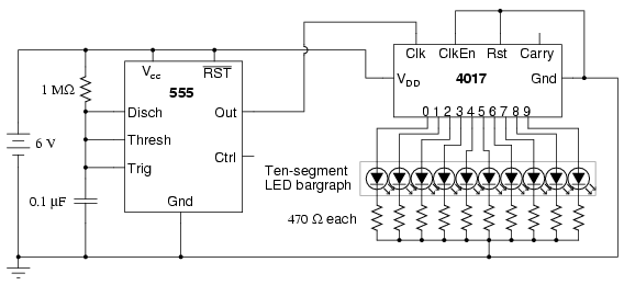
For those looking to enhance the circuit's efficiency, the eight 1N914 diodes used for wire ORing can be replaced with a dual 4-input OR gate, such as the CD4072, which can simplify the design and reduce the component count while maintaining functionality. This modification could also improve reliability and reduce potential points of failure in the circuit.The LED traffic Light circuit controls 6 LEDs (red, yellow and green) for both north/south directions and east/west directions. The timing sequence is generated using a CMOS 4017 decade counter and a 555 timer. Counter outputs 1 through 4 are wire ORed using 4 diodes so that the (Red - North/South) and (Green - East/West) LEDs will be on during the first four counts.
The fifth count (pin 10) illuminates (Yellow - East/West) and (Red - North/South). Counts 6 through 9 are also wire ORed using diodes to control (Red - East/West) and (Green - North/South). Count 10 (pin 11) controls (Red - East/West) and (Yellow - North/South). The time period for the red and green lamps will be 4 times longer than for the yellow and the complete cycle time can be adjusted with the 47K resistor.
The eight 1N914 diodes could be subsituted with a dual 4 input OR gate (CD4072). 🔗 External reference
Related Circuits
The title contains numerous words because this instructable integrates various concepts from multiple sources. The primary idea originated from Robomaniac's Desktop Energy Seed Lamp, combined with Witch's Growing Plants with LED Lights instructable and various wick gardening planters. The...
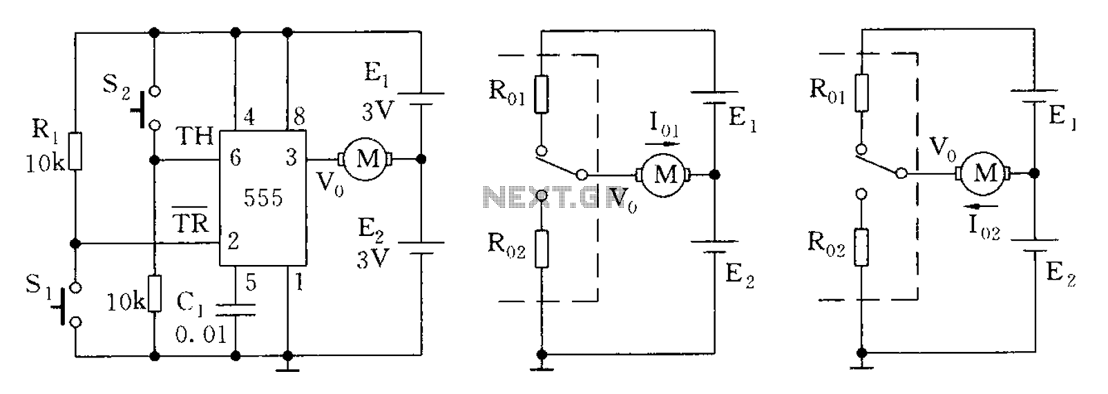
The 555 timer in bistable mode has fewer applications compared to its stable and monostable modes. Bistable mode refers to the circuit configuration based on the R-S (Reset-Set) trigger mode. An example of this is a micro-motor reversing control...
For optimal lifespan, it is recommended to operate LEDs at 20-25 milliamps (mA). However, in certain LED flashlight conversions, including many commercial LED flashlights, the LEDs are often driven at 50-60 mA, which is twice the rated current. Testing...
This circuit can be utilized by individuals, such as a gentleman summoning his butler, a manager calling for his secretary, or, as in the author's case, to call children down for dinner without raising one's voice over the noise...
This circuit is constructed around a 555 timer and utilizes very few components. Due to its simplicity, even beginners can easily assemble and use it as a control device. A readily available laser pointer can be employed to operate...
The following circuit illustrates a schematic diagram of an LED sequencer. This circuit is based on the 555 timer integrated circuit (IC). Features include a 555 timer circuit designed to debounce a mechanical switch, a 555 timer circuit to...