
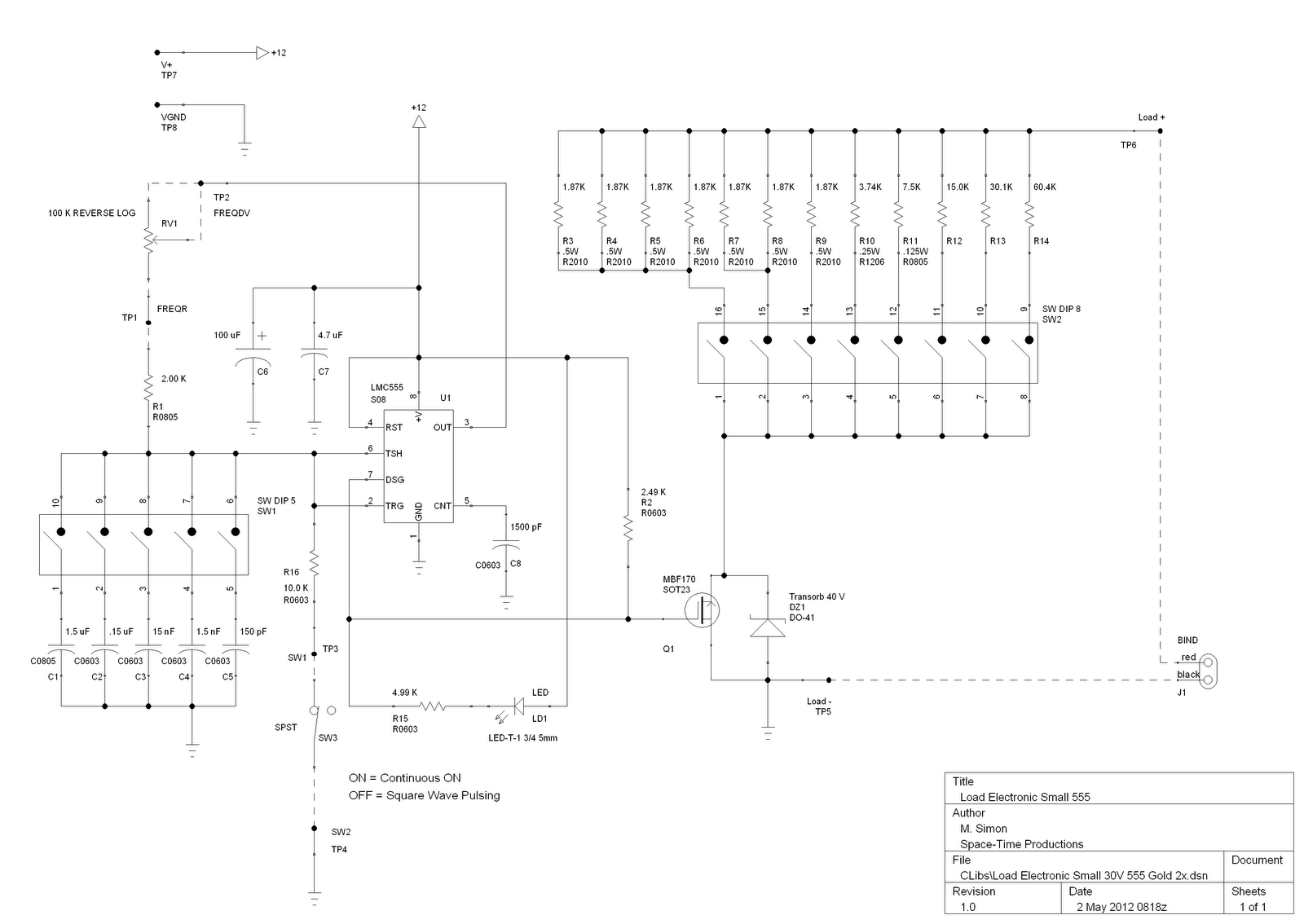
A control circuit diagram 555 pairs steady mode

The 555 timer IC is a versatile component commonly used in various electronic circuits. In bistable mode, the 555 timer operates as a flip-flop, allowing it to maintain its output state until it receives a triggering pulse. This mode is particularly useful in applications where two stable states are required, such as in memory storage, toggle switches, or motor control circuits.
In the context of a micro-motor reversing control circuit, the bistable configuration allows for the control of the motor's direction. The circuit typically consists of a 555 timer, resistors, capacitors, and the micro-motor itself. When a trigger pulse is applied to the reset or set pin of the 555 timer, it changes the output state, thus reversing the direction of the motor.
The circuit diagram for this application would illustrate the connections between the 555 timer and the motor, as well as the necessary components to ensure proper operation. Resistors are used to set the timing characteristics, while capacitors may be included to filter noise or stabilize the power supply. The output of the timer directly controls the motor driver circuit, which may include transistors or relays to handle the motor's power requirements.
Overall, the bistable mode of the 555 timer offers a reliable solution for controlling devices such as micro-motors, providing a simple yet effective means of toggling between two states based on external inputs.555 bistable mode, stable and non-stable than single modes of application is relatively less. Bistable mode means that the circuit composed by R-S trigger mode. As shown by a m icro-motor reversing bistable mode control circuit diagram. 7b9bd92f536999.jpg onload if (this.width 620) this.wih 620; onclick window.open (this.src) style cursor: pointer alt Click to enlarge /
Related Circuits
This audio mixer circuit does not utilize a low impedance input to mix non-ideal sources; instead, it employs multiple amplifiers to provide ideal sources prior to mixing through simple resistors. An ideal source is characterized by low impedances, which...

Lithium-based (Li+) batteries are increasingly used in portable devices due to their favorable characteristics. However, they are often in limited supply, leading to long lead times unless a preferred-customer status is established with manufacturers. Consequently, a backup alternative to...
This is a license to use the files to manufacture up to 12 boards. If additional boards are required, please make contact. It is important to note that the order must specify the intent to produce 12 or fewer...
The circuit can be constructed using a pair of twin-T oscillators, with the Q factor adjusted to the threshold of oscillation, allowing them to resonate like a bell when activated by a voltage pulse. Each twin-T oscillator is designated...
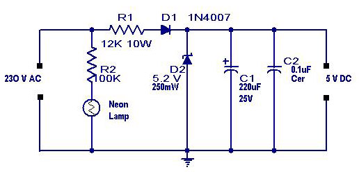
A simple transformerless power supply circuit with a diagram and schematics that provides a 5 volts DC output. This is a low-cost, low-current power supply circuit suitable for simple applications such as powering an LED. The transformerless power supply circuit...

The call is triggered by the position sensing circuit, which activates the control circuit and SOS alarm circuit. This system is designed for critically ill patients or to assist disabled individuals in the event of a fall. A position...