
LES produced using blackout emergency lighting

The described circuit is a critical power management system designed to ensure continuous lighting during power failures. The primary components include a light source (H1), a backup light (H2), a relay (J), and a transistor (VT) which acts as a switch. The LSE (Light Sensing Element) monitors the AC power supply status. Under normal operating conditions, when the 220V AC supply is stable, H1 serves as the primary light source, illuminating the area. The high output from the LSE keeps the transistor VT in the off state, preventing the relay from engaging and keeping H2 turned off.
Upon detecting a power outage, the LSE output drops, triggering the conduction of transistor VT. This change activates relay J, which connects the power supply to lamp H2, thereby illuminating it as a backup light source. This automatic switching mechanism ensures that there is minimal disruption in lighting, which is particularly vital in environments requiring constant illumination, such as medical facilities.
The circuit's design emphasizes reliability and simplicity, ensuring that the transition between H1 and H2 is seamless, thereby providing a practical solution to power interruption challenges. The use of a relay for switching between light sources allows for a robust method of maintaining lighting without the need for manual intervention. This automated system is particularly beneficial in critical applications, enhancing safety and operational efficiency during unexpected power outages. Circuit operation principle of the device shown in Figure 11. Power outages are frequent thing, but some occasions, the power does not allow (such as the ongoing surgery, etc.) . LSE with simple circuit design, fully automated. When 220V AC, the lamp H1 lights up, while the LSE feet high output, transistor VT end, the relay J is released, it does not shine direct light H2. Once a power outage, H1 off, LSEs pin output low, then transistor VT conduction, the relay J pull, turn the power lights H2, H2 light automatically convert between almost two lights interruption.
Related Circuits
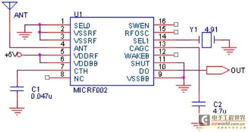
The maximum coverage of the RSR232 serial port transport protocol is 10 meters, which poses significant challenges for remote transmission control. To address this issue, a design has been developed utilizing ultra-high frequency (above 300 MHz) for transmission. This...
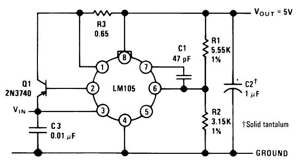
A single diffused, wide base transistor, such as the 2N3740, is recommended due to its reduced tendency to cause oscillation issues compared to double diffused, planar devices. Additionally, it exhibits greater reliability under overload conditions, and low-cost options are...
Interface the LCD with the 8051 microcontroller AT89S52. However, upon powering up the microcontroller, the LCD displays only black boxes. Multiple codes have been tried, but the output remains the same. The circuit has been simulated in Proteus, where...
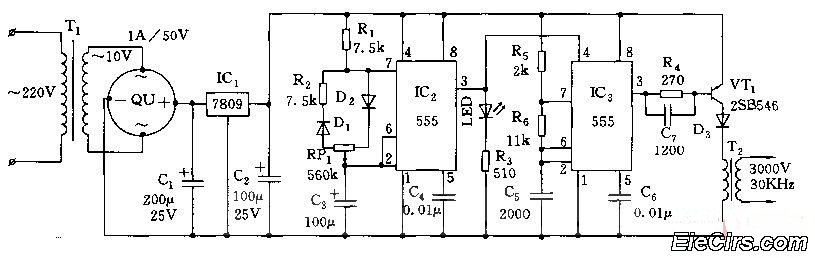
Adjust the RP1 to modify the pulse duty cycle of IC2, which in turn alters the pulse oscillation time of IC3. This regulation allows for the control of ozone generation time, effectively changing the concentration of ozone in the...
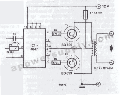
The inverter circuit features the CMOS 4047 as its primary component, converting a 12V DC voltage to a 220V AC voltage. The 4047 operates as an astable multivibrator. A symmetrical rectangular signal is generated at pins 10 and 11,...
This circuit is a simple analog multiplier. The operation of the circuit can be understood by considering A2 as a controlled gain amplifier. It involves components such as an analog multiplier, a log-antilog circuit, and a summing junction, along...