
LF356 Wide Range Current-To-Voltage Converter

A current-to-voltage converter, also known as a transimpedance amplifier, is primarily utilized to convert an input current signal into a corresponding output voltage signal. This type of circuit is particularly useful in applications such as photodetectors, where the output is a current generated by light exposure, and it needs to be converted into a voltage for further processing.
In its simplest form, the circuit consists of a resistor (R) connected to the output terminal. When an input current (I_in) flows through the resistor, Ohm's Law (V = I × R) dictates that a voltage (V_out) will be developed across the resistor. The output voltage can be expressed as V_out = I_in × R, where V_out is the voltage across the resistor, I_in is the input current, and R is the resistance value.
The choice of resistor value is critical in determining the sensitivity and range of the circuit. A higher resistance will produce a larger output voltage for a given input current, but may also increase noise and reduce bandwidth. Conversely, a lower resistance will yield a smaller output voltage but may provide better performance in terms of speed and noise immunity.
For practical applications, additional components such as operational amplifiers (op-amps) may be integrated into the design to improve performance characteristics, such as input impedance, gain stability, and noise reduction. In these configurations, the op-amp can be used to buffer the output, thereby isolating the load from the current-to-voltage conversion stage and allowing for more precise voltage readings.
Overall, the current-to-voltage converter is a fundamental circuit that serves as a building block in various electronic systems, enabling the effective translation of current signals into voltage signals for further analysis or processing.Current to voltage converter circuit can be made using a single resistor, it is very simple since any current will naturally develop a voltage when flow through. 🔗 External reference
Related Circuits
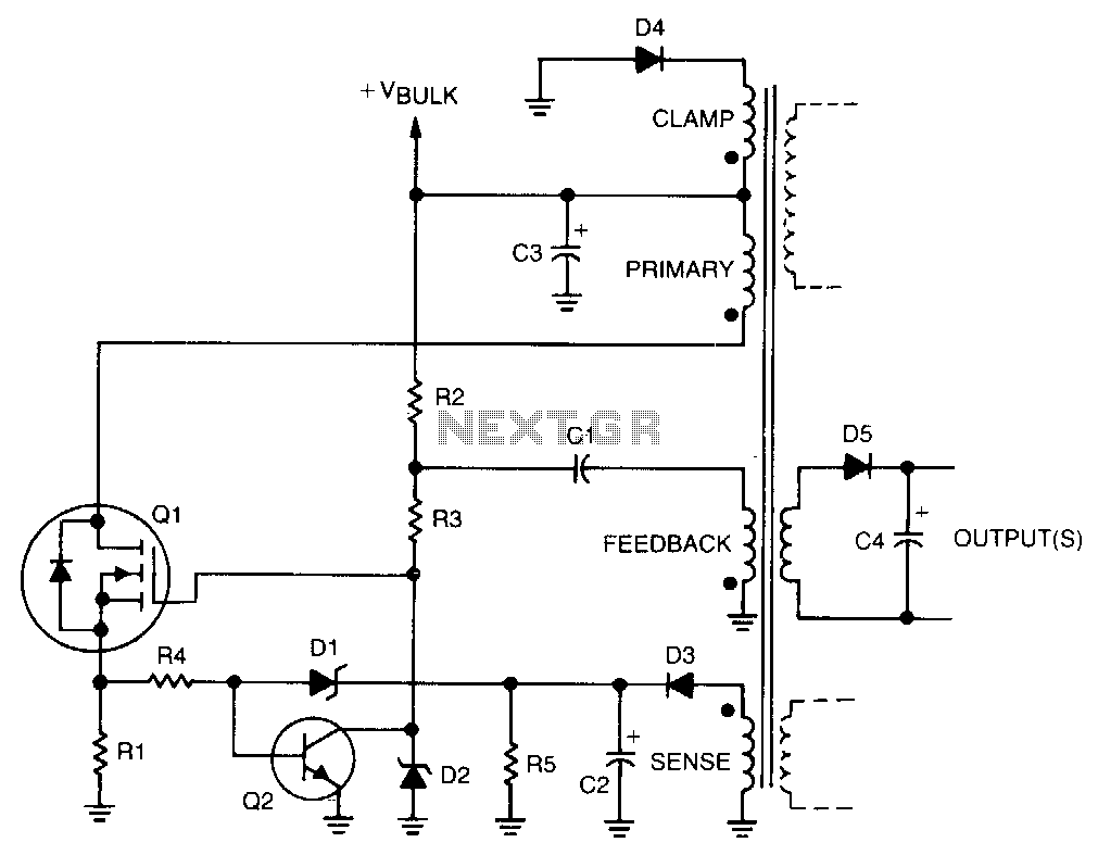
Regulation is achieved by using the rectified output from the sense winding, which is applied as a bias to the base of transistor Q2 through Zener diode D1. The collector of Q2 then disconnects the drive from the gate...
The objective is to enhance information transmission by utilizing articles. Please contact us via email at [email protected] within 15 days if there are any issues related to article content, copyright, or other concerns. The articles will be removed promptly. To...
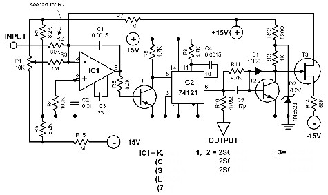
This voltage-to-frequency converter is designed to connect to a frequency counter to display the measured voltage value. This converter-counter combination creates an inexpensive yet functionally complete digital voltmeter. The circuit outputs TTL-compatible pulses that are 5 µs wide. The...
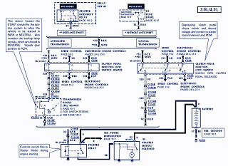
The part of the 1995 Ford Ranger wiring diagram includes components such as the transmission range sensor, electronic engine control, clutch pedal position switch jumper, speed control, automatic transmission, starter interrupt relay, relay box, starter motor during engine starting,...
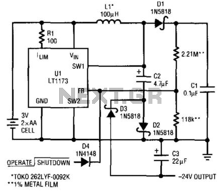
This circuit utilizes a Linear Technology LT1073 to function as a -24 V converter. The power supply can consist of two AA cells (3 V) or a 5 V source. The circuit is capable of delivering a current of...
Below is the schematic diagram of an audio input module. This module is capable of producing a DC output voltage that is proportional to the amplitude of the input signal. The audio input module typically consists of several key components...