
lfr using 555 timer

The sensor component is the most crucial part of the line-following robot, as it guides the robot to stay on track. The LDRs (Light Dependent Resistors) serve as the "eyes" of the robot. Long wires are used to connect these sensors to the circuit, allowing flexibility in positioning the sensor board for optimal structure and performance. The LEDs in this section remain continuously illuminated. When the LEDs shine on a black surface, there is no reflection, causing the LDRs to remain dark, which allows the motors to run. Conversely, when the LEDs detect a white line, the light is reflected, causing the LDRs to trigger the motors to turn off. In the robot's structure, the sensor part is not fixed; therefore, it is essential to incorporate a mechanism to securely attach the sensor to the robot's chassis for improved functionality. Maintaining a low height for the sensor part is recommended to enhance efficiency.
The circuit design emphasizes simplicity and effectiveness, ensuring that even those with limited electronic experience can construct a functional line-following robot. The use of 555 timers for control and LDRs for sensing provides a robust solution for the task of line following, making it an excellent project for both educational and practical applications in robotics.This is Simple and cheap approach to Line Following Robot, This do not have anymicro controller but just a simple basic Circuit on three 555 timers. It has a good efficiency on following all kind of curves. This Robot is no more than 1000PKR. To make a reliable and well functioning robot, you just not need Electronics Skills but also a little Mech
anical too. Having a Electronics mind, the most difficult job I felt in making this robot was Tires which would fit Properly in my motors and the Structure of Robot. For these stuff I accessed my University`s Lathe Machine for tires and a Wood Work shop to make the Structure.
Does this circuit looks difficult to you ! wana go for a simpler than this !Click hereto see my Differential Drive based Line following Robot made on just BC108 Transistors. This is complete Diagram of whole circuit for Line Following Robot, but I have not shown the connections for LEDs, So for that, you will have to connect two LEDs in series of 1k resistor with +ve and -ve of this circuit.
Dont feel that this is any difficult circuit, its very simple if you notice that Both 555 Timer circuits(others except center one) are exactly same. So you actually need to built the following two circuits. Our motors are not directly connected to the outputs of 555 Timer, but a transistor is used as a switch.
The Pin Configuration of this transistor is (1)Emitter, (2)Base & (3)Collector I name this Part of the Circuit as Motor Driver Circuit, Now this is a circuit in which our DC geared motors are to be Hooked up, So wee need to make two circuits like this one in which The pin no 2 (Trigger) is given input from the Center 555 Timer Circuit In the above images It is configured as monostable, that means when they are triggered they give a pulse on the ouput pin which is then connected to transistor as switch circuit for motors Sensor part: This is the most important part of the LFR, because it has the sensor which guides the robot to move on Line and donot leave the track EveR ! These LDRS are the eyes of the LFR. As you can see i have kept long wires which i have later connected to circuit, the reason for taking long wires is to be free of placing this strip sensor board anywhere suitable to structure and for perfection.
The LEDs in this part, are all the time ON. The reflection of LEDs is sensed by LDRs. When LEDs are on black area there is no reflection and LDRs are dark (Motors Run) but when LEDs see white line the LDRs are shone some light and hence trigger the Motors to turn off In my Structure as you see in Video, My sensor part is not fixed. When you design your chasis of Robot, must have any technique to fit the sensor part Fixed in the structure.
Make sure to keep sensor part height to be as lowest as possible for higher efficiency 🔗 External reference
Related Circuits
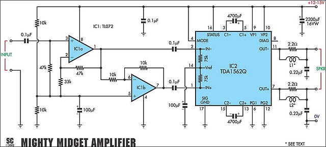
It is based on a Philips class-H audio amplifier integrated circuit and can deliver 36W RMS or 70W music power, all from a 13.8V supply. The new Mighty Midget Amplifier can produce approximately 36W RMS continuously into a 4-ohm...
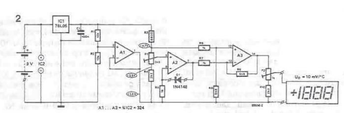
A simple thermometer can be constructed using operational amplifiers and a standard or protective diode, such as the 1N4148, as depicted in the electronic diagram below. A constant reference voltage is supplied to the non-inverting input of the operational...
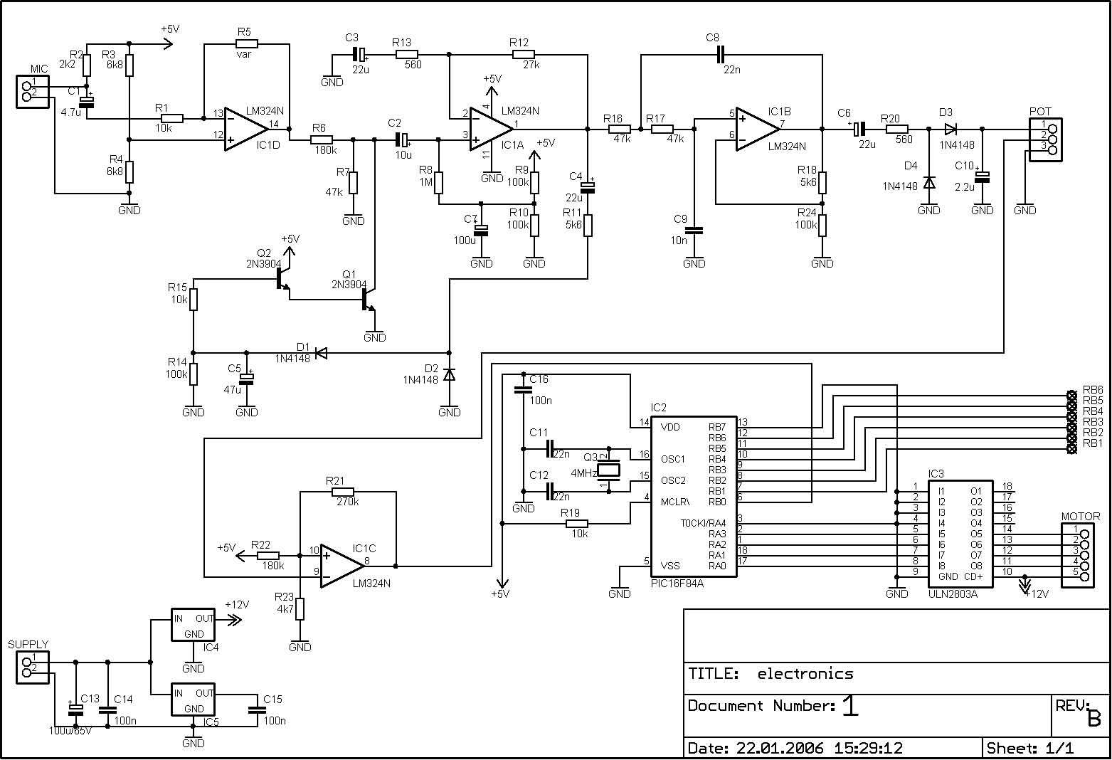
The PIC microcontroller is capable of controlling a motor after each beat, with the option to bypass certain beats using pushbuttons. The rotation speed and duration can also be adjusted within specified limits to prevent register overflow or underflow....
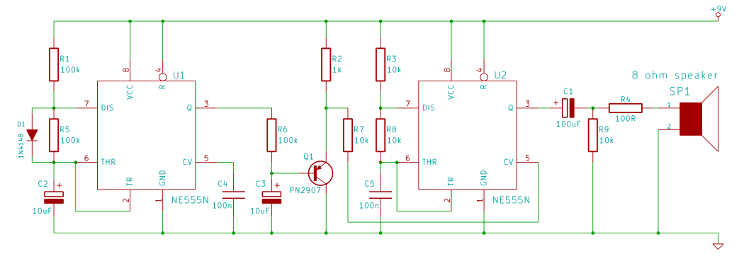
This tutorial outlines the construction of a wailing siren that produces a tone with varying pitch. The circuit incorporates two 555 integrated circuits (ICs) and a loudspeaker. The wailing siren circuit is designed to create an audio effect that simulates...
A power transistor with a voltage drop of 4 volts and a current of 3 amps may dissipate approximately 12 watts of heat, presenting a challenge in series regulators. In contrast, a saturated transistor or MOSFET with a voltage...
The LM386 is a widely recognized and effective option for various designs that necessitate a compact audio power amplifier (1-watt) integrated into a single chip. However, the LM386 requires... The LM386 is a low-voltage audio power amplifier that is commonly...