
Lie Detector Circuit

The electronic lie detector circuit operates on the principles of galvanic skin response (GSR) and heart rate monitoring to assess physiological changes in the subject's body. The circuit typically consists of a microcontroller, sensors, and a display unit.
The GSR sensor measures the electrical conductance of the skin, which varies with moisture levels influenced by sweat gland activity. This response is often heightened during stressful situations, such as when a person is lying. The heart rate sensor, usually an optical sensor, detects changes in blood flow and pulse rate, which can also indicate emotional distress.
The microcontroller processes the signals from both sensors, analyzing the data to produce two distinct outputs. The first output represents the subject's response to difficult questions, while the second output reflects their emotional state, providing insights into their honesty or stress levels during the interrogation.
The circuit can be designed with an LCD or LED display to visualize the readings in real-time. Power supply considerations are essential, as the circuit may require a stable voltage source to ensure accurate sensor readings. Additionally, calibration of the sensors is necessary to account for individual differences in baseline physiological responses.
Overall, this electronic lie detector circuit serves as a tool for understanding human emotions and truthfulness through measurable physiological responses.This electronic lie detector circuit project will give two readings: one for difficult questions for the subject and another to show its emotional state in.. 🔗 External reference
Related Circuits

This second-order low-pass filter utilizes a 741 operational amplifier and can be tuned from 2.5 kHz to 25 kHz. The circuit is beneficial in audio and tone control applications. R1 and R2 are ganged potentiometers. The described circuit features a...
This page provides information on circuits that can trigger stroboscopes from external circuits. The circuits are designed to be integrated into stroboscope systems, allowing them to be activated using an external trigger pulse. The standard trigger pulse utilized in...
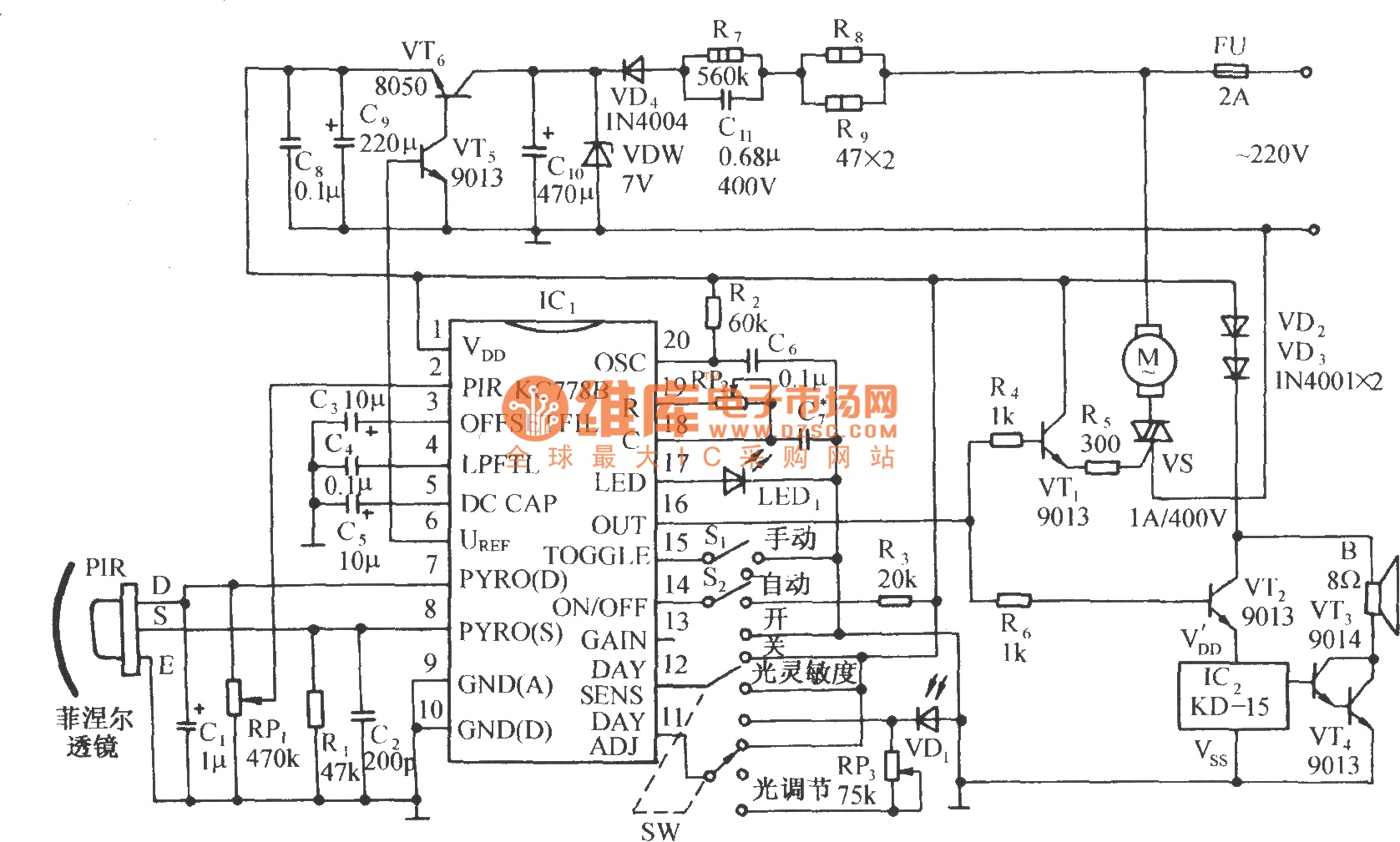
The circuit is depicted in the diagram. It is a control circuit that consists of the infrared-specific integrated circuit KC778B, which serves as the central component. Surrounding it are a pyroelectric infrared sensor head (PIR), a light control and...
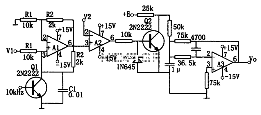
As illustrated in the dividing circuit diagram, A1 consists of a voltage-controlled current source, A2 functions as a voltage comparator, and A3 is configured as an active low-pass filter. When the time constant R1C1 is equal to the clock...
The circuit consists of an ultrasonic transmitter and a receiver that operate at the same frequency. Ultrasonic piezoelectric transducers serve as the output and input devices, respectively, with their frequency of operation determined by the specific devices used. The...
The circuit depicted in Figure 3-93 is integrated with an optical phase sequence protection relay. The circuit in question is designed to provide phase sequence protection using an optical relay mechanism. Optical phase sequence protection relays are crucial in applications...