
light activated led scr

The light-activated LED circuit featuring an SCR is a practical application of semiconductor technology, showcasing the unique properties of SCRs in switching applications. SCRs are four-layer, three-junction devices that can be turned on by applying a small gate current, making them ideal for controlling larger loads like LEDs in response to light levels.
The circuit operates by integrating an LDR, which serves as a light sensor. Under low light conditions, the LDR exhibits high resistance, preventing current flow through the SCR. As ambient light increases, the resistance of the LDR decreases, allowing sufficient current to flow to the gate of the SCR. This gate current triggers the SCR into conduction, creating a path for current to flow through the LED, thus illuminating it.
The inclusion of a 50K variable resistor allows for fine-tuning of the light sensitivity. By adjusting this resistor, the threshold at which the SCR turns on can be modified, enabling the user to set the desired light level for activation. This feature is particularly useful in applications where varying light conditions are present.
The circuit's power supply can be sourced from a 6V battery or a compatible power supply, ensuring that it operates efficiently in various environments. The simplicity of this design makes it suitable for educational purposes, as well as practical applications in automatic lighting systems, where the LED can serve as an indicator or a functional light source based on ambient light conditions. Overall, this light-activated LED circuit effectively demonstrates the principles of light sensing and solid-state switching using SCR technology.The schematic shown below is a circuit of light activated LED using SCR. SCR (Silicon Controlled Rectifiers) or thyristor are physically looks like transistors but their internal circuit and working procedure is totally different as compare to the transistors. Both SCR and transistor can work as In this circuit the SCR is working as a switching de vice. When the LDR will receive light its resistance will decrease which will switch on the SCR and the LED becomes activated. The 50K variable resistor is used to adjust the amount of light on which you want to switch on the SCR and activate the LED.
The circuit can be operated with 6V battery or power supply. 🔗 External reference
Related Circuits
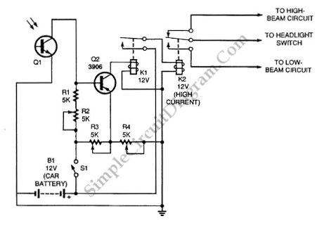
Automatic headlight dimmer circuit diagram for a car's headlight. This circuit ensures maximum brightness for optimal visibility while automatically switching when necessary. The automatic headlight dimmer circuit is designed to enhance driving safety by adjusting the brightness of the vehicle's...
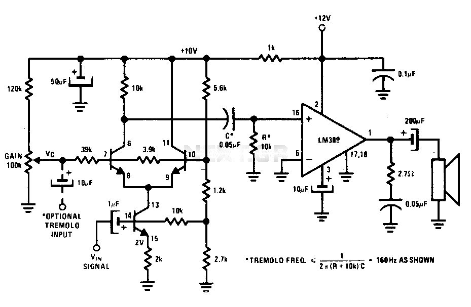
The transistors create a differential pair with an active current-source tail. This configuration, referred to as a variable-transconductance multiplier, produces an output that is proportional to the product of the two input signals. The multiplication effect arises from the...
This circuit diagram represents a radio-controlled system, commonly used in toy car applications for children. The circuit consists of two main parts: the transmitter and the receiver. The transmitter generates radio signals using an oscillator circuit formed by transistor...
The receiver, as depicted in the figure, assists patients in avoiding missed audio signals during the daytime. The receiver operates independently, and the lighting will automatically turn off. At night, the lighting signal receiver activates simultaneously with the patient's...
Activates a mobile transceiver or other mobile equipment when power is applied, especially if the external circuit is interrupted during theft. The transmitter will then emit an unmodulated carrier signal even if the Push-To-Talk (PTT) switch is disconnected or...
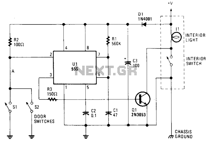
The circuit maintains the courtesy light's illumination for 30 seconds after the door is closed. The lead from the door switch is disconnected and linked to the 555 timer circuit. The 555 timer is configured in monostable mode and...