Light Chaser Ii
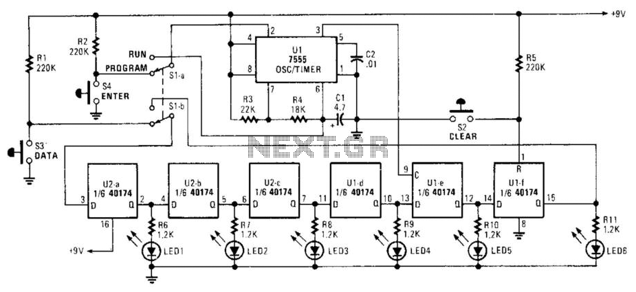
Up to six lights can be sequentially flashed using this circuit. LED1 through LED6 can be replaced by optocouplers (MOC3010, etc.) to control 120-Vac loads via triacs. Ul generates pulses that clock the shift register mode of the six D flip-flops in the CD 40174. By using switch S1 A-B, the register can be programmed either ON or OFF (low or high) and then switched to run in the programmed sequence. Switch S2 clears the program.
This circuit design facilitates the sequential flashing of up to six lights, which can be implemented with standard LEDs or optocouplers such as the MOC3010 for controlling higher voltage AC loads through triacs. The circuit utilizes a CD40174 integrated circuit, which contains six D flip-flops that function as a shift register. The operation begins with a pulse generated by a timing circuit (Ul), which clocks the flip-flops in the shift register mode, allowing for the sequential control of the connected lights.
The programming of the shift register is managed through switch S1, which allows the user to set the desired state of each flip-flop to either ON (high) or OFF (low). This enables the user to determine the sequence in which the lights will flash. Once programmed, the circuit can be switched to run the predefined sequence, providing a controlled and repeatable light display.
To reset or clear the programmed sequence, switch S2 is utilized, which resets the states of the flip-flops within the CD40174, allowing for a new sequence to be programmed. The use of triacs in conjunction with optocouplers allows for the isolation of the low-voltage control circuit from the higher voltage AC loads, ensuring safety and reliability in operation.
Overall, this circuit is versatile and can be adapted for various applications requiring sequential light control, such as decorative lighting, indicators, or signaling devices. The ability to modify the connected loads and the programming of the sequence provides flexibility in design and implementation. Up to six lights can be sequentially flashed using this circuit. LED1 through LED6 can be replaced by optocouplers (MOC3010 , etc.) to control 120-Vac loads via triacs. Ul generates pulses that clock the shift register mode up of the six D flip-flops in the CD 40174. By SI A -B, the register can be programmed either ON or OFF (low or high) and then switched to run in the programmed sequence. S2 clears the program.
