
Sound To Dancing Lights Converter With 9013 Transistor

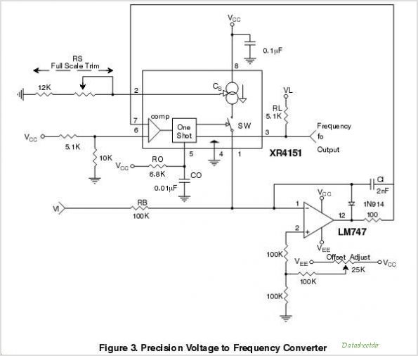
The audio signal conversion circuit is designed to process audio signals efficiently while maintaining signal integrity. The circuit architecture includes a buffer/amplifier stage, which is crucial for isolating the input signal from the output load and providing necessary gain. This stage typically employs operational amplifiers (op-amps) configured in a non-inverting arrangement to achieve high input impedance and low output impedance, ensuring minimal loading effect on the previous stage.
Following the buffer/amplifier stage, the circuit incorporates three distinct filter circuits. These filters serve to manipulate the frequency response of the audio signal, allowing specific frequency ranges to be enhanced or attenuated. The design may include a low-pass filter to eliminate high-frequency noise, a high-pass filter to remove low-frequency hum, and a band-pass filter to isolate a specific frequency range of interest. Each filter can be implemented using passive components such as resistors, capacitors, and inductors, or active components like op-amps, depending on the desired performance characteristics.
The overall design of this audio signal conversion circuit aims to optimize sound quality and fidelity by carefully selecting component values and configurations. Proper layout and grounding techniques are also essential to minimize interference and ensure stable operation. This circuit finds applications in various audio processing systems, including mixers, equalizers, and amplifiers, where precise audio signal handling is critical.The simple circuit for converting an audio signal. The circuit basically consists of a buffer/amplifier stage and three filter circuits: a .. 🔗 External reference
Related Circuits
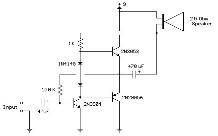
Improved 3 Transistor Audio Amplifier. The load resistor for the driver transistor is connected directly to the positive supply. This configuration has a disadvantage in that as the output moves positive, the voltage drop across... The improved three-transistor audio amplifier...
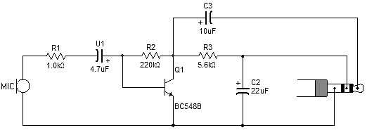
Most sound card microphone inputs require a minimum signal level of at least 10 millivolts, but some older 8-bit cards need as much as 100 millivolts. The typical impedance of the PC sound card microphone input is in the...
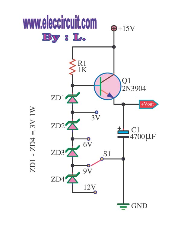
This is a DC regulator circuit that can provide multiple output voltages simply. It functions as a simple step-down DC converter and is designed with a fixed resistor R1. The described circuit operates as a DC voltage regulator, specifically designed...
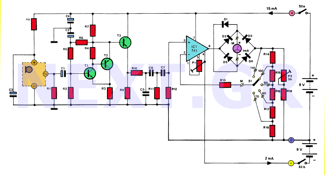
The human ear can detect sounds ranging from 20Hz to 20KHz, with the normal range typically between 100Hz and 13KHz, depending on an individual's age and health. For accurate measurements, a range of 20Hz to 20KHz is used. Sounds...
The purpose of this application note is to present an example circuit illustrating the operation of the XR-T5683 device at a data rate of 10.1 Mbps. This note includes the results of measurements taken on the XR-T5683 at this...
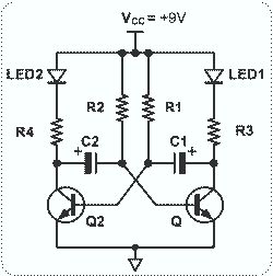
This circuit is straightforward and easy to construct, utilizing two transistors as active components along with several passive components such as resistors, capacitors, and two LEDs. The circuit employs the MPS2222 transistor, though any NPN type transistor can be...